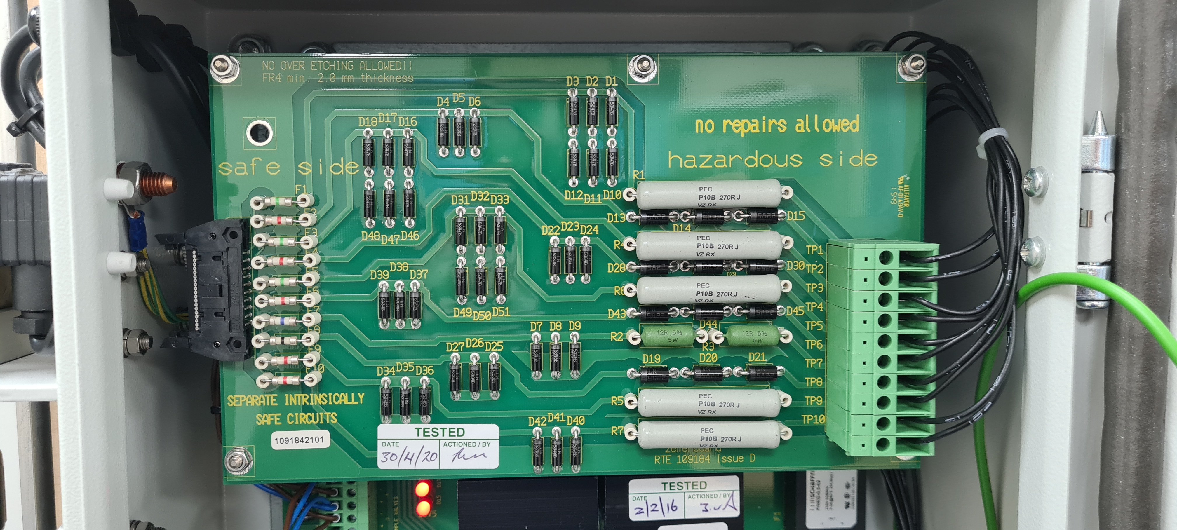
The Zener Barrier PCB is mounted inside the Zener barrier module of the Smart ODME system. This module is usually located in the ships foam / fire room or other indoor, non-hazardous area within close proximity to the ODME VPC.
This PCB when installed correctly ensures that no sparking can occur in the event of equipment failure that is located in the hazardous / explosive atmosphere.
The Zener barrier module must always be mounted in a non-hazardous location that is clean, dry and does not suffer extremes of temperature.
If equipment in the hazardous area is damaged or fails, this can also damage the Zener Barrier PCB.
There is no visible method of identifying the condition of the PCB So some simple checks will need to be performed using a MultiMeter.
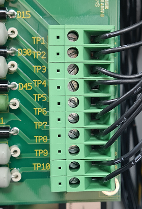
The Hazardous side of the PCB is on the right. A row of terminals can be found here labelled TP1 through to TP10. These wires will pass back out into the hazardous area so it is crucial that no voltages are passed along here without the Zener barrier PCB in place.
These checks will look for voltages on the hazardous side that confirm that the fuses on the PCB have not blown and are still making a circuit.
The following points should be measured to confirm that the Zener barrier is healthy whilst all electrical power is ON to the system;
TP1 to TP2
These terminals are used if a second flow meter is installed on the ODME system. If the system only has one flow meter, no measurement is necessary here (Or a 0V reading may be obtained). If two flow meters are installed, a measurement of approximately 27mV shall be found here. Any voltage above 0v DC shows that the Zener has not blown.
TP3 to TP4
These terminals are used flow the primary flow meter of the ODME system. A measurement of approximately 27mV DC shall be found here. Any voltage above 0v shows that the Zener has not blown.
TP5 to TP6
This is connected to the pressure transmitter and a value of approximately 17.5V DC should be present.
TP7 to TP8
This is the power supply to the ODME measuring cell and operates between 7V DC and 9V DC. If no voltage is measured across these terminals then the Zener has blown.
If there is a voltage here but the voltage measures below 6V, the large Zener barrier PSU PCB has failed and will need replacing.
TP9 to TP10
these terminals pass the RS485 communications between the measuring cell and ODME computer module. A very small fluctuating voltage can be found here at around 300mV to 600mV.
If any of these terminals do not produce the required voltage, the Zener Barrier PCB Must be replaced in full. This is not repairable under hazardous area regulations.
Do not install and energise a replacement PCB until the fault causing the failure has been identified and resolved.
Always triple check wiring.