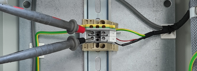
- Ensure that all supplies are available to the ODME system. First is to check that you have Voltage of ~19VDC across the pair of wires from Zener barrier module to the flow meter totaliser. This should be measured across terminals 1+2 of the flow meter totaliser.
- If there is no voltage here, double check that the wiring is correct and also measure the voltage across terminal TP5 and TP6 of your Zener barrier module PSU PCB (Large PCB at the back).
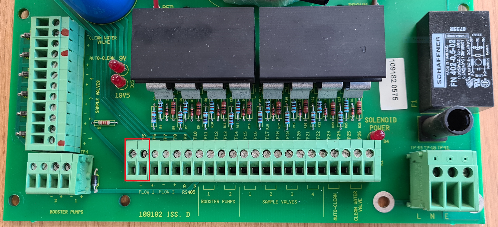
If no voltage is present across TP5 and TP6 of your Zenr barrier PSU PCB, the PCB Will need replacing. - Now with your multimeter set to measure mA DC, disconnect the positive wire from from the terminals within the flow meter totaliser module and connect your multimeter probes in series as below.
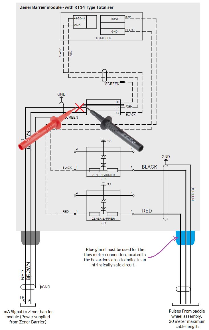
With no flow, you should see a 4mA signal at your multimeter. This signal will increase as the flow increases.
If you see a voltage of ~19VDC yet the mA Output is not present, the flow meter totaliser is at fault.