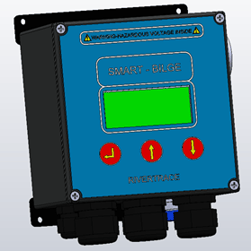
The Smart bilge controller PCB is located in the left hand module of your Smart Bilge, behind the enclosure cover and LCD Display. This PCB handles and stores IMO Log data, controls relays and emits a mA Output, holds the time and date alongside driving the display. All Controller PCBs are supplied pre-programmed and ready for use.
Always carryout an IMO download prior to working on your smart bilge monitor to ensure that the data remains safe at all times.
Antistatic precautions should always be taken when handling electronic components and printed circuit boards.
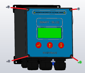
To remove the Controller PCB you must first isolate all power to the system, including any power that may be applied through external alarms or devices connected to the alarm relays. Once all power is isolated, the front panel of the Controller enclosure can be removed by unscrewing the 4x philips screws positioned in each corner.
Once the four screws are removed, the cover can be lifted. You can temporarily refit the cover to the top of the module meaning you don’t have to disconnect the cables attached to lid however care needs to be taken not to damage the ribbon cable or earth lead. (Lid removed in further pictures for clarity)
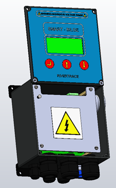
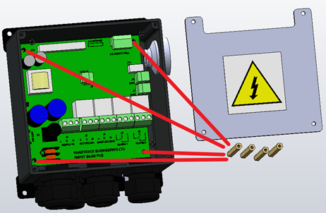
With the cover fitted in the service position, the clear plastic hazard screen is exposed. This should now be removed by unscrewing the 4x flat head screws in each corner of the screen.
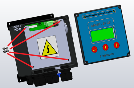
Once the hazard screen is removed you will need to remove all electrical connections to the PCB (make note of where they came from for fitting to the new board - It can be useful to mark the plugs with a permanent pen).
All cables can be unplugged without the need to unscrew any terminals. This will mean using your existing plugs with your new PCB and fitting the new plugs to the original PCB. Once all plugs are removed from the PCB, remove the spacers which held the hazard screen on, and also holds the PCB down.
With the spacers removed, the PCB is free to be removed. This can be tight but lifting the left side of the PCB first will help the PCB clear the measuring cell communications cable.
Refit the new PCB following the guide in reverse, double checking all connections prior to applying any voltages.