The following information gives instructions on how to replace a matched OCD CM or CW Cell & Processor. At all times while swapping parts inside the monitor casing ensure that all electrical supply to the monitor is ‘off’ and that anti-static precautions have been taken.
- Replacing the Cell
Disconnect the ribbon cable connecting the cell to the main PCB. Unscrew the 4 x M5 hex headed screws located on the inside of the enclosure on the right-hand side. The cell can now be removed. Place the new cell in the same position as the old and replace the screws and ribbon cable. - Replacing the Processor
The CM / CW processor is located on the display PCB which is attached to the lid of the enclosure (this does not need to be removed to replace the chip).
Locate the IC labelled as U4 – this is the CM / CW processor. Simply remove the old processor and replace with the new one in the correct orientation. - Connecting clean water to the cell
Connect the Instrument to a supply of clean air free water and allow this to flow through the Instrument for a few minutes. It is crucial that the clean water is very clean and bubble free. It can take up to 30 minutes of flushing for some fresh water supply lines to clear.
Ensure flow rate is between 0.5 and 2.0 litres per minute.
If Flowing clean water is unavailable, a static clean water sample may be used by connecting the outlet to the inlet and pouring clean water into the cell. In both cases ensure cell has been cleaned using a bottle brush before proceeding. - Power up the monitor
Ensuring the monitor has the correct mains jumper settings and the correctly rated supply is connected to the Live, Earth and Neutral terminals, turn the monitor ‘on’. - Entering the Engineering Functions (see diagram for details)
To enter the Engineering Functions menu, a combination of keys need to be pressed. First, the SECRET KEY must be depressed with the SET/ZERO KEY and held for a period of no more than 1 second. The DOWN KEY must then be pressed within 3 seconds of this action. If the operation is successful the display will show EF and all display LED’s will be on, otherwise the display will remain unchanged. - Setting the T Channel value on the display (see diagram for details)
Using the UP and DOWN keys select the T channel (TC on the display) and press the SET/ZERO KEY to view. The display should read between AE and B2 (B0 or B1 is optimal), if not adjustment can be made via the variable resistor – R11 on the main board. Once this is complete press the SET/ZERO key again. The display should now show TC again. Leave the monitor until the display changes to EF then press the SET/ZERO key to enter normal monitor mode.
The Secret button is not visibly marked on the membrane and can only be identified by feeling the indentation in the position highlighted below.
OCD CM USER INTERFACE LAYOUT
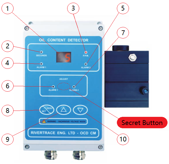
| ITEM No. | DESCRIPTION | ITEM No. | DESCRIPTION |
| 1 | PPM DISPLAY | 6 | ALARM 1 AJUST LED |
| 2 | SECONDS LED | 7 | ALARM 2 AJUST LED |
| 3 | PPM LED | 8 | SET/ZERO KEY |
| 4 | ALARM 1 INDICATION LED | 9 | UP KEY |
| 5 | ALARM 2 INDICATION LED | 10 | DOWN KEY |
-
Cell and Chip Components
These are classified as consumable items and therefore do not require return for recalibration. -
Complete Unit (Controller + Cell)
If recalibration or repair is needed, the entire unit, including both the controller and the cell, must be returned to ensure proper servicing and recalibration.