Overview
The raw OCD Xtra calibrated parts consist of the measuring cell, main analog PCB and digital PCB. These parts must always remain as a set and if mismatched, the calibration is void and may produce error messages. All parts that are consumable or exposed to wear should also be replaced at the same time.
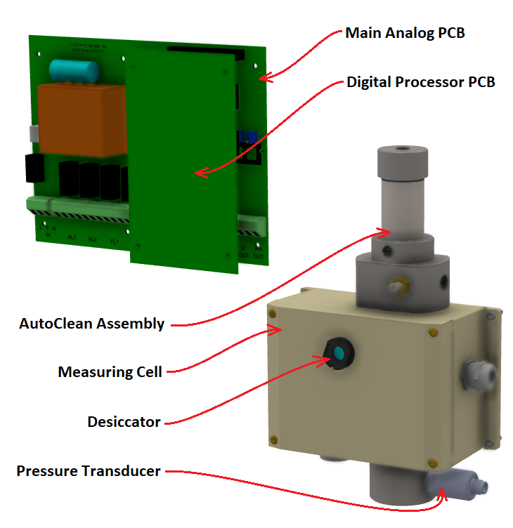
Replacing these parts onboard is a delicate process that requires a complete strip and rebuild of the computer module. Recognizing the complexity of this work in a field environment, Rivertrace supply the calibrated parts pre-mounted, allowing for a quick, simple and trouble free process. This results in a far more economical approach as damage, mismatching or incorrect installation is ruled out. The added benefit here is that the PCBs always remain protected throughout their journey from the Rivertrace factory to use in the field.
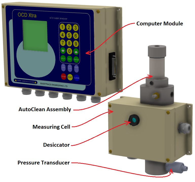
Replacing the Computer module and measuring cell assembly
(Calibrated Parts)
Replacing the calibrated parts is a simple task that requires no special tools.
Existing parts removal
Step 1 - Before any work is carried out, or the system is electrically isolated, it is important to record all settings within the menu so that you can re-enter these into your new computer module once installed.
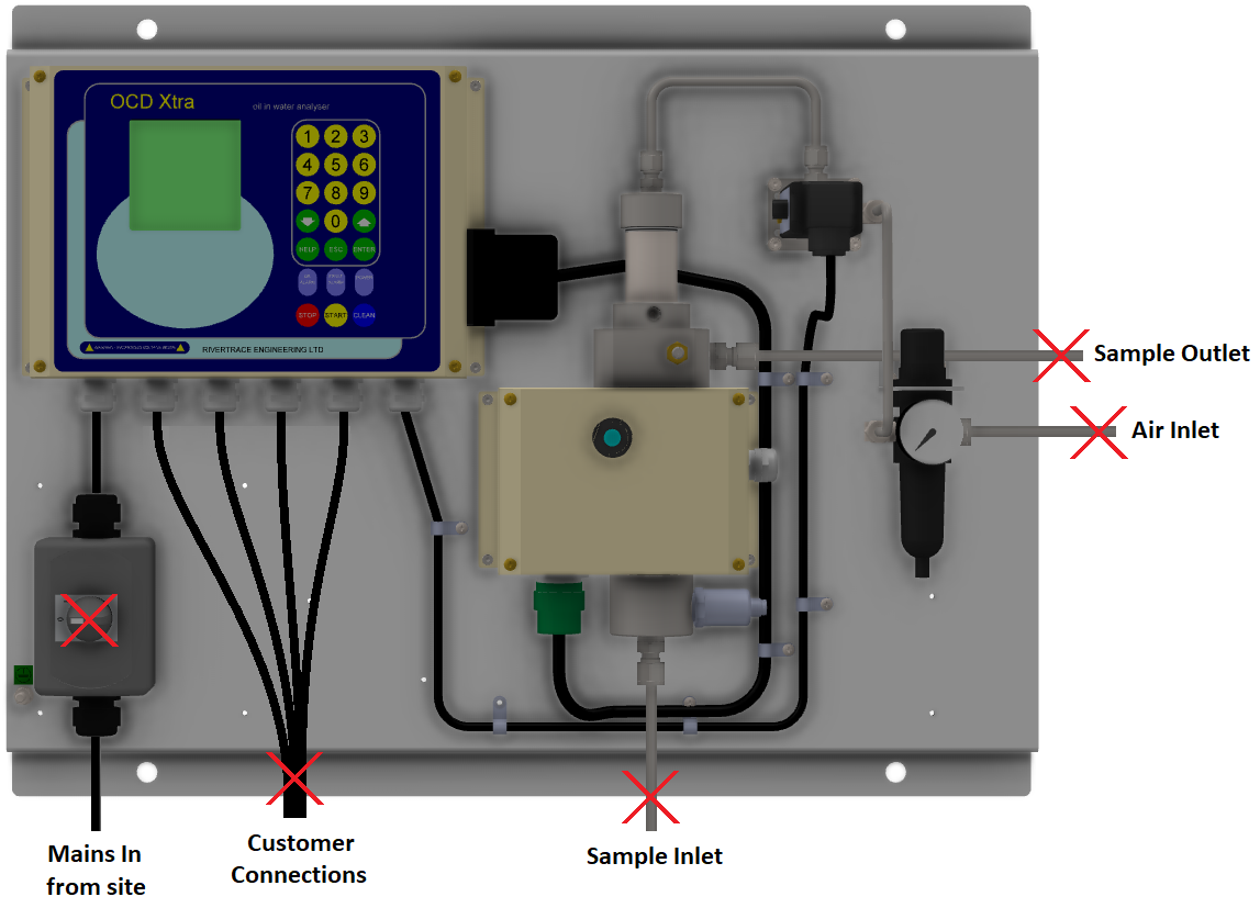
Step 2 - Ensure that all supplies and connections are isolated, including any external electricity that may be present at the alarm relays from the sites alarm systems or valve control systems. Drain all fluid from the system.
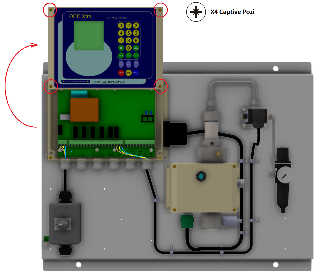
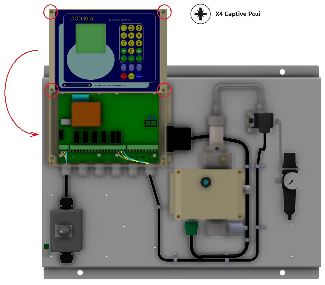
Step 3 - Loosen the four captive Pozi screws from the display panel and remove the display panel from the computer module. Fix it into the service position as shown below. Be very careful that the display isn't dropped as this will damage the ribbon cable that connects the display panel to main analog PCB.
Step 4 - Remove the clear plastic safety cover that covers the main analog PCB by unscrewing the 8x captive Pozi screws. Double check with a multi meter than no voltages are present across any of the screw terminals within the computer module.
Step 5 - Mark up and remove all wires from the main PCB terminal rail and then remove the cables from the cable glands.
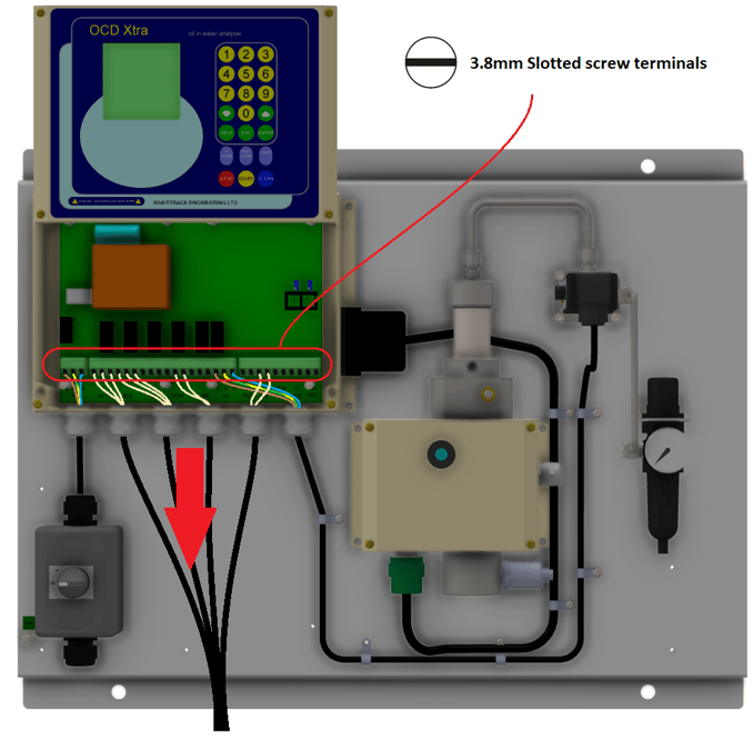
Step 6 - Refit the front display panel to keep the internals safe in storage or transit.
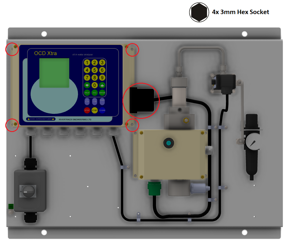
Step 7 - Disconnect the communications cable from the side of the computer module enclosure, support the computer module and remove the 4x 3mm hex head screws securing the computer module to the backplate. The computer module can now be lifted away and stowed safely.
Step 8 - Disconnect the 1/4" Stainless pipe from the top of the Autoclean actuator and top of the solenoid valve and store aside safely. You must also remove the entire fitting from the top of the Autoclean assembly as you will need to refit this in your new assembly.
Step 9 - Disconnect the pipework and fittings from the inlet and outlet ports of the measuring cell. Keep the fittings safe to refit into your new measuring cell.
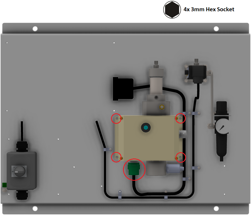
Step 10 - Disconnect the bayonet type communications cable from the bottom of the measuring cell and support the measuring cell whilst removing the 4x 3mm Hex head screws that secure the cell to the backplate. The cell can now be lifted away and stowed safely alongside the paired computer module.
Removal complete!
The removed parts can be returned to Rivertrace for assessment, repair and recalibration. These make great onboard spares.
Refitting new parts
Step 1 - Fit the pipe fittings into the measuring cell that were removed from your old measuring cell. Use the correct sealant for Stainless steel components within the application. Do not use PTFE tape.
Step 2 - Hold the measuring cell in position and secure using the 4x 3mm hex head screws. Connect the bayonet type communications cable to the bottom of the measuring cell.
Step 3 - Fit the fitting that was removed from the old Autoclean into your new Autoclean and reconnect the 1/4" Stainless pipe between the Autoclean and the solenoid valve.
Step 4 - Refit all pipework to the measuring cell utilising the pipe fittings removed from the original measuring cell.
Step 5 - Hold the new computer module in position and secure using the 4x 3mm hex head screws. Connect the communications cable to the communications D type connector in the right side of the computer module.

Step 6 - Loosen the four captive Pozi screws from the display panel and remove the display panel from the computer module. Fix it into the service position as shown below. Be very careful that the display isn't dropped as this will damage the ribbon cable that connects the display panel to main analog PCB.
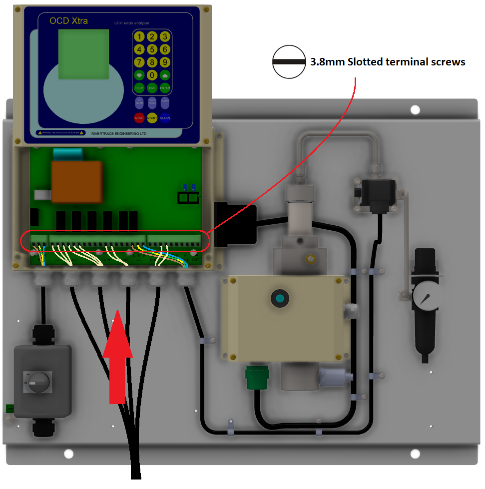
Step 7 - Feed the cables back through the correct cable glands and re-terminate the wires according to notes taken prior to disassembly. Ensure that the cable clangs are secure and grip the cable correctly.
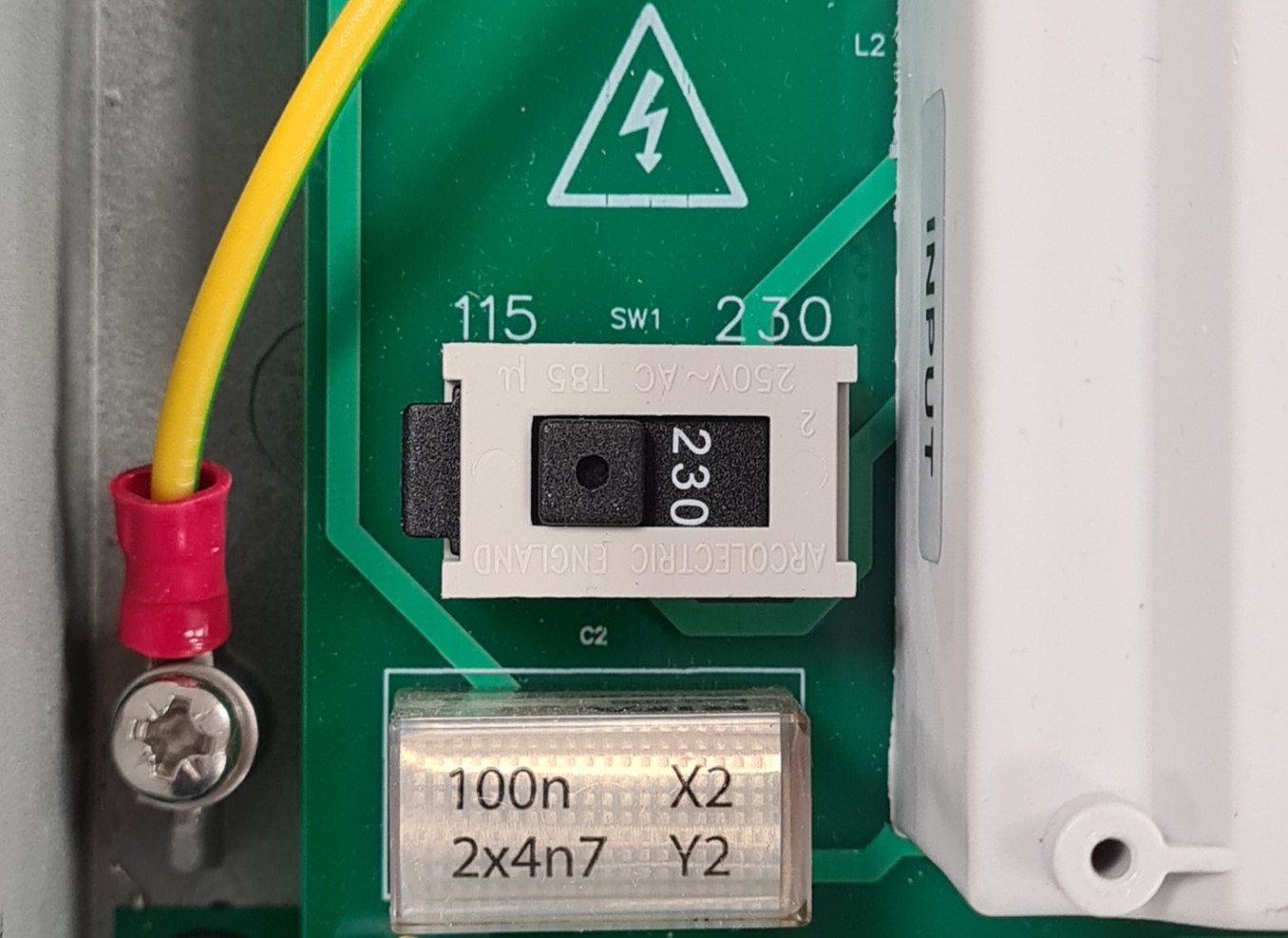
Step 8 - Double check that the voltage selector switch on the main analog PCB is in the correct position, depending on the supply voltage available to the system (Should be the same as the computer module removed). This will be either 110VAC or 230VAC.
Step 9 - Refit the clear plastic safety screen on top of the main analog PCB then refit the display panel to the front of the computer module.
Step 10 - Remove all isolations and visibly check for any signs of leakage. Resolve an leaks from fittings where necessary.
Step 11 - Turn the OCD Xtra ON and ensure all settings match the settings recorded from the original computer module.
Refit Complete.