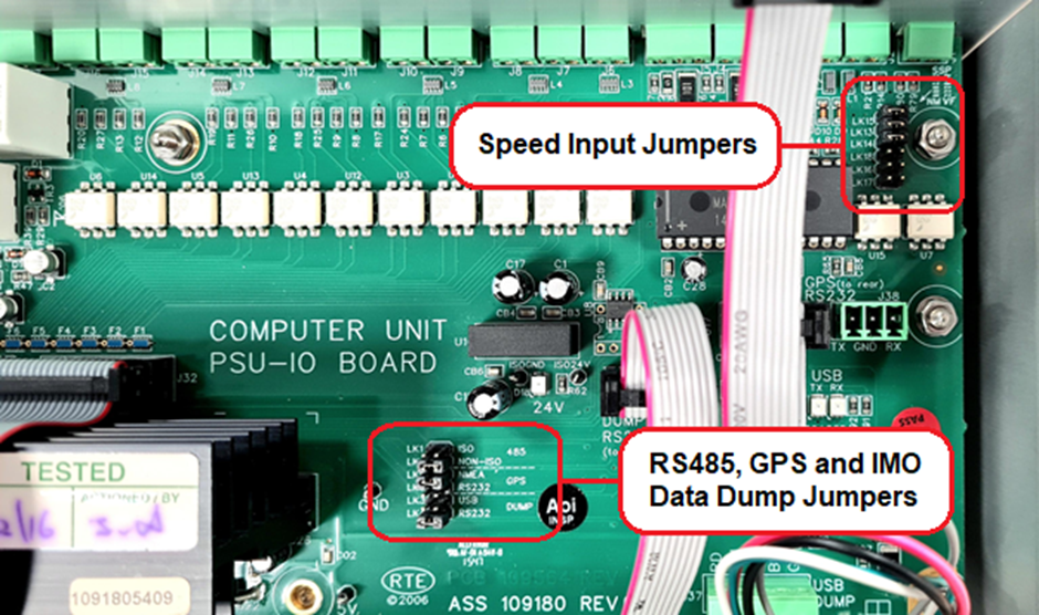
Within the Smart ODME computer module, on the large PSU / IO PCB, there are two significant clusters of hardware jumpers that need to be set for the system to function. These jumpers are vessel specific so must be set during the installation and commissioning phases.
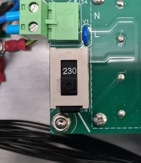
Voltage Selection
Before energising any new Smart ODME computer module, it is crucial that the voltage selector is set correctly. The voltage selector switch is positioned on the main IO PSU PCB of the ODME Computer module and allows the engineer to select between either 115VAC or 230VAC Inputs. Never energise the ODME computer with the switch set incorrectly as this may cause permanent damage to the IO PSU PCB.
Speed Input Jumper settings
The ships speed log should pulse 200 times for each nautical mile that is covered by the vessel. The ODME Computer will then calculate the speed using the built in clock and the speed pulses from the vessel (Giving distance travelled).
The engineer must first understand the type of speed pulse being transmitted from the ships speed log - Volt Free or NMEA. Volt free pulses are simply contacts that open and close 200 times per nautical mile, depending on the ODME Computer to provide the voltage that operates the circuit. NMEA Pulses emit a small voltage pulse 200 times per nautical mile and do not require any voltage to be supplied by the ODME Computer. If the vessel is stationary, no pulses will be detectable. ODME Computer settings depend on the type of speed pulses that the vessel supplies.
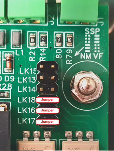
If the vessel uses volt free speed pulses, make sure the vessels speed log is connected to J2 at the rear of the computer. This will be two wires. Pins LK15, LK13 and LK14 should then be linked with the three jumpers supplied, whilst LK16, LK17 and LK18 are left open circuit as below:
In the ODME Computer module software settings, viewed via the display and navigated using the buttons, the Speed Input setting should be set to "SHIP".
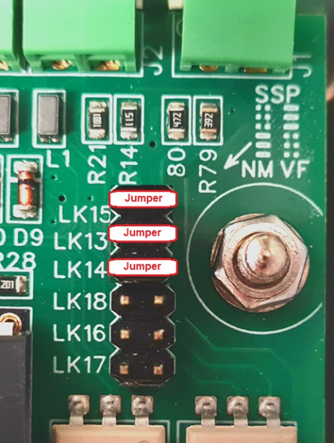
If the vessel uses NMEA Speed pulses, make sure the vessels speed log is connected to J2 at the rear of the computer. This will be two wires. The Speed input Jumpers are located on the large IO PCB Positioned in the base of the computer module. Pins LK16, LK17 and LK18 should be linked with the three jumpers supplied, whilst LK15, LK13 and LK14 are left open circuit as below:
At the ODME Computer module software settings, viewed via the display and navigated using the buttons, the Speed Input setting should be set to "GPS".
RS485, GPS and IMO Data dump jumper settings
The 485 jumper dictates which RS485 port is used to communicate with the Smart ODME Measuring cell. The RS485 is always terminated in J5 at the rear of the ODME computer module which is the non-isolated RS485 port. This means that the jumper should always be set to “NON-ISO”.
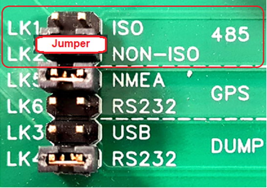
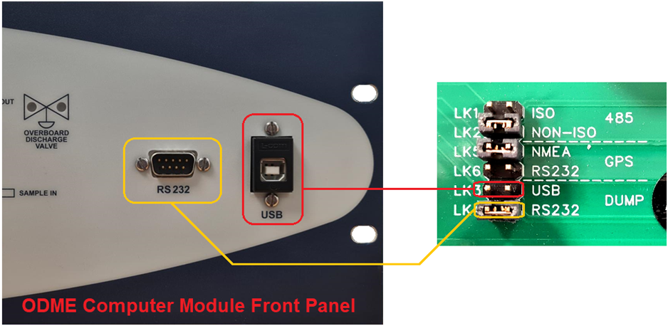
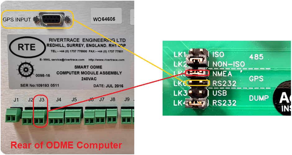
The GPS jumper depends on how the GPS input is wired. When the GPS is wired to the J3 terminal to the rear of the ODME computer the jumper must be set to “NMEA”. When the GPS Is wired to the RS232 serial connector, the jumper must be set to “RS232”.
The Dump jumper depends on how the user will opt to download the IMO data. When the USB Cable is used via the USB port, the jumper must be fitted on the “USB” pins. When the user will connect to the serial RS232 port, the jumper must be fitted to the “RS232” pins.