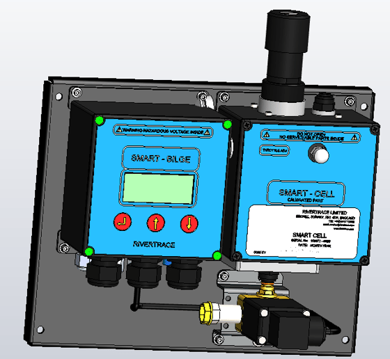
This article will talk you through how to replace the measuring cell of your SmartBilge oil content meter. Replacing the measuring cell can resolve multiple issues including high PPM readings and communications failure. The measuring cell is an intelligent, digital part of the system that captures, calculates and shares the PPM value with the SmartBilge controller module.
The Smart Bilge measuring cells are NOT voltage specific. This means that any replacement Smart Bilge measuring cell can be used on any Smart Bilge monitor, regardless of supply voltage or special software settings.
Important note - Your new measuring cell will not be supplied with the manual clean (Or AutoClean if fitted). It is critical that you retain your cleaning device onboard, to install into your new measuring cell.
Most importantly, replacing the measuring cell will give the SmartBilge monitor a new calibration certificate.
Please ensure that all Flow and power is isolated to the monitor before any work is carried out, including any additional power that may enter the SmartBilge monitor via external alarm systems.
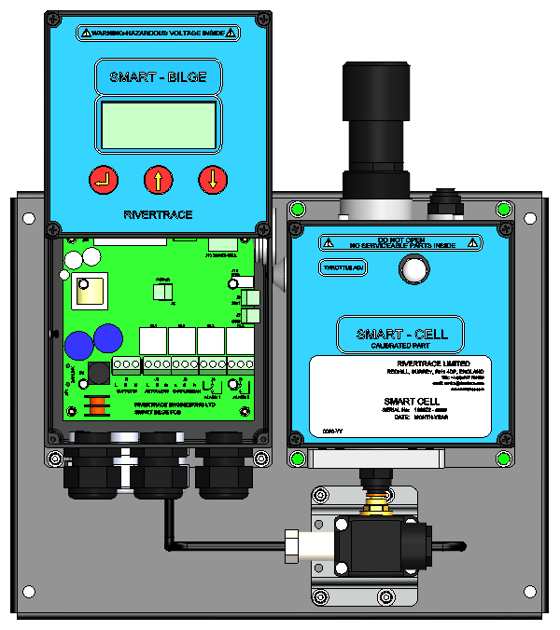
The first stage to remove the Smart bilge measuring cell is to undo the 4 screws securing the Smart bilge control module display panel. These are fitted with 'O' rings, be sure not to lose these. (Highlighted green)
Use 2 of the screws to loosely secure the Lid as shown however be sure not to damage the cables when doing so.
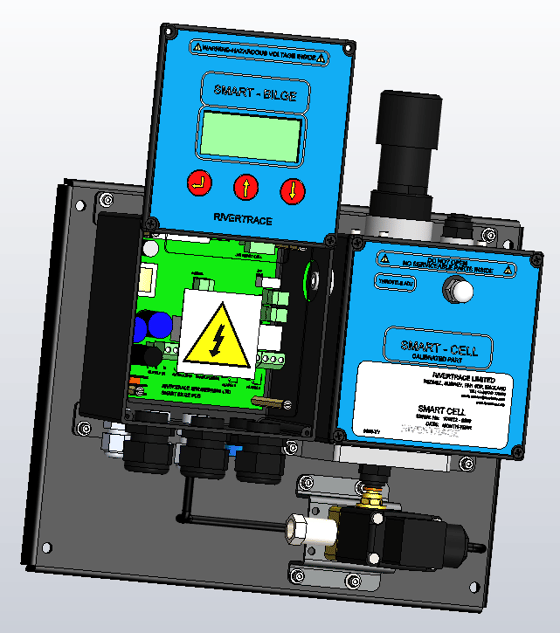
Next remove the Perspex Safety Cover, undo the 4 retaining screws which are fitted with retaining washers which should keep the screws attached to the cover plate. Put the cover plate and screws to one side.
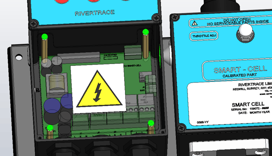
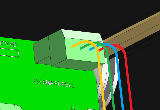
The 4 core communications cable between the measuring cell and the controller PCB can now be removed. This is located at the top right-hand corner Identified as J15. Inside the Smart bilge controller module, the connector can be pulled off from the PCB to aid removal of the cable. Record the positions of each colour core and remove from the connector block by releasing the terminal screws. Place the connector block back onto the PCB to ensure it is not lost.
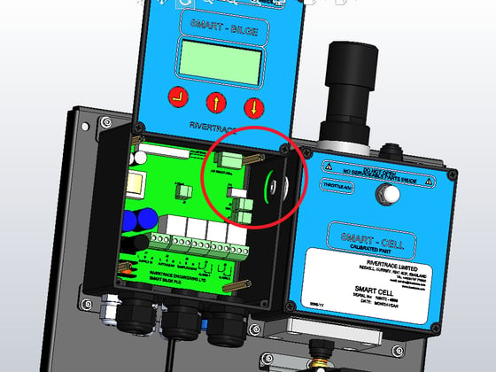
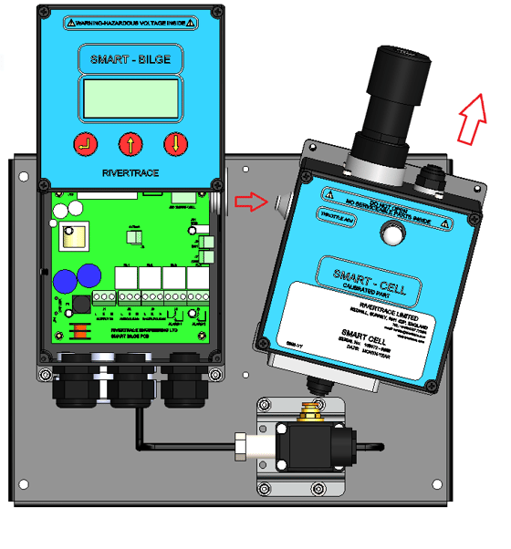
The four 4mm Allen screws can now be removed that secure the measuring cell to the SmartBilge back plate. These are highlighted green in the image below.
The measuring cell can then be pulled away from the chassis, away from the controller and upwards. You will need to release the black plastic push-in fitting during this process.
The new measuring cell can now be refitted, using the cleaning device removed from your previous measuring cell. Using this procedure in reverse order, ensure the 4 core communications cable is wired into the controller PCB as below;
Yellow, Green, Blue and finally Red.
Ensure that the control module components are refitted and the cover of the control module is sealed. All pipework must be refitted correctly and checked for leaks.
To verify the accuracy of the new SmartBilge measuring cell, a Rivertrace supplied, product specific Verification kit can be used here by crew if required.