The SmartBilge monitor is designed to record the state of the separator in the IMO log. This is to satisfy MEPC.107(49) guidelines and failure to utilize this function will result in noncompliance.
The controller PCB has a 2-pin terminal called SW1 designated to monitor the separator status by sending 5Vdc down one pin and show the separator as status ON in the IMO Data when 5Vdc is received back down the other pin. If no 5Vdc signal is received back, the separator status will show as OFF in the IMO data.
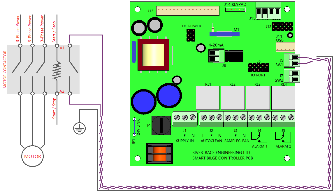
For this to function, the terminal must be connected to a volt-free switch that closes when the separator is running. If no suitable output is provided by the separator, the motor contact is the ideal point to find this volt free switch as the motor contactor may have a spare pair of terminals to utilise.
No voltage should ever be put into the J9 SW1 input as this will cause permanent damage to the controller PCB. The Controller PCB supplies its own voltage and must only be switched by external equipment.
Twisted pair, Screened cable must always be used for this input to avoid induced energy entering the controller PCB and causing irreversible damage. The cable screen must be securely terminated at a suitable ground. at the separator end of the cable.
Below is a diagram to show how the separator input status should be connected if a spare pair of suitable volt free contacts are available at the motor contactor;
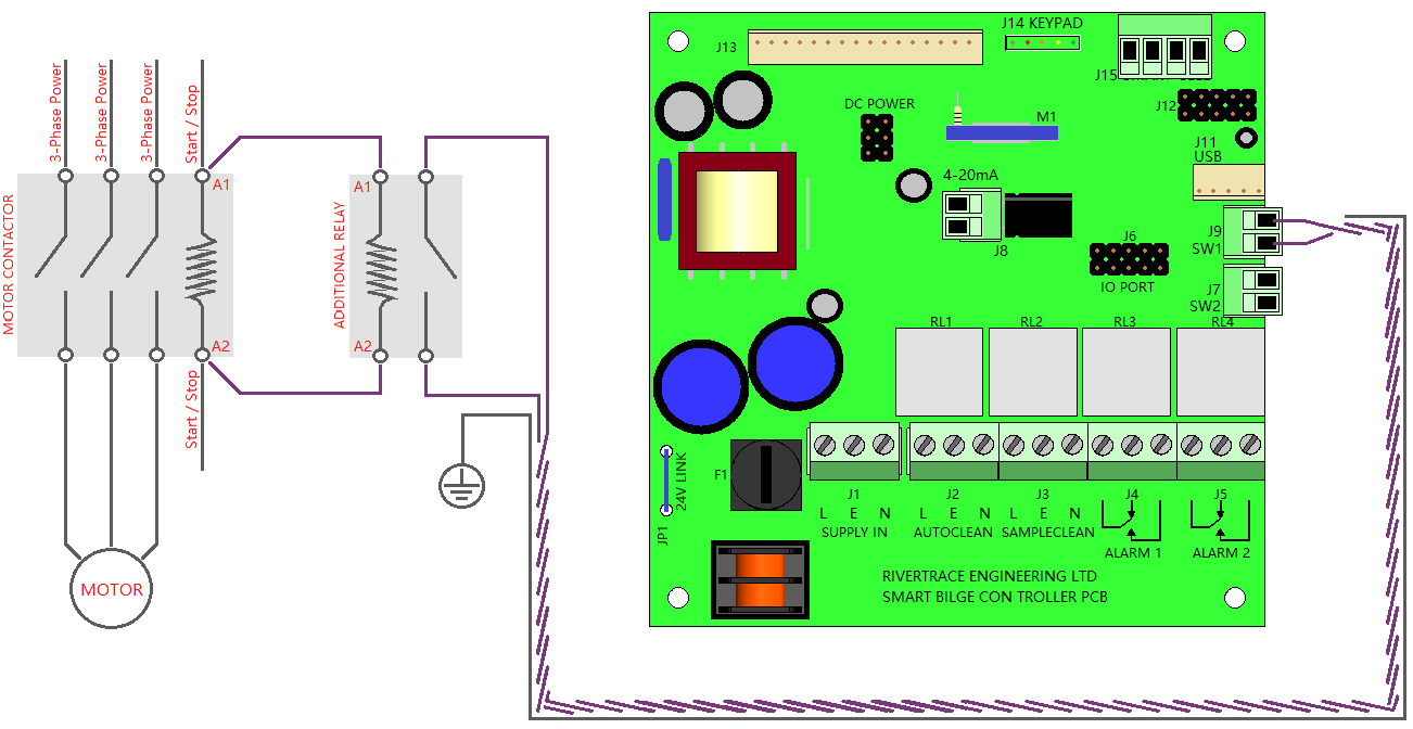
If No spare volt free contacts are available at the motor contactor, an additional relay must be fitted, in parallel with the existing pump start / stop voltage supplied by the separator. This is typically connected to terminals named A1 and A2 but ultimately, you are looking for the coil of the motor contactor.
You must ensure that the additional relay that you are fitting is the correct voltage to suit the voltage present across the coil of the motor contactor.
Twisted pair, Screened cable must be used for this input to avoid induced energy entering the controller PCB.
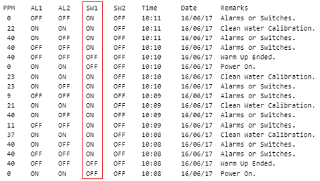
Once the installation is complete, you must always ensure that this status is recording in the IMO data correctly. A new row of IMO data will be recorded each time the separator pump is turned ON or OFF, showing a change of state for the SW1 (Separator Status Input) Column as below;
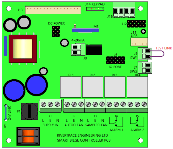
If you are not seeing a change in status at the SW1 column each time the separator is turned ON or OFF, this can be tested by simply removing the wires connected to the SW1 input of the SmartBilge controller PCB and linking the to terminals together as below, using a short length of wire.
If the SW1 input status does not change state whilst manually linked for testing, the controller PCB is at fault and must be replaced. If the SW1 Input status does change correctly when manually linked, there is an issue with the wiring, relay or switch in the circuit external to the SmartBilge monitor that must be identified and corrected.