The controller PCB has a 2-pin terminal called SW2 designated to induce a flushing state within the SmartBilge monitor. When the two pins of SW2 are linked together, all alarms will lock to an "ON" position to prevent any discharge whilst the 3-way sample / clean valve is energised to allow fresh water to flush the measuring cell. The display will also show the following:

SW2 is typically connected to volt free N/O contacts within the OWS that close when the OWS is in a backflush or maintenance state. The Smart Bilge will supply 5VDC down one pin of the terminal so that when the OWS Contacts close, the 5VDC is received back at the other pin.
The SW 2 state is recorded in the IMO Data. SW2 will appear as ON when the pins are linked and will appear as OFF when the pins are not linked.
No voltage should ever be put into the J7 SW2 input as this will cause permanent damage to the controller PCB. The Controller PCB supplies its own voltage and must only be switched by external equipment.
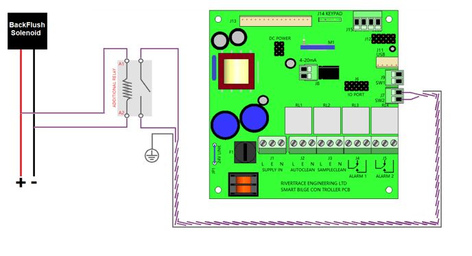
If No spare volt free contacts are available at the OWS Control module, an additional relay must be fitted, in parallel with a flushing solenoid valve or similar, that energises when flushing takes place.
You must ensure that the additional relay that you are fitting is the correct voltage to suit the voltage present across the solenoid valve that you are using as your trigger.
Is it critical to check that the SW1 and SW2 plugs to not ever get swapped as they have very different functions. SW1 is also required to comply with MEPC.107(49) regulations whereas the SW2 input is optional.