
Paddle wheel installation
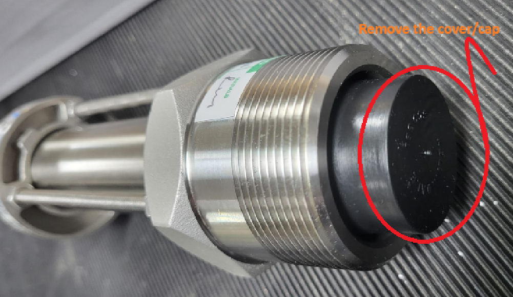
Before install the flow meter, please remove the cover/cap.
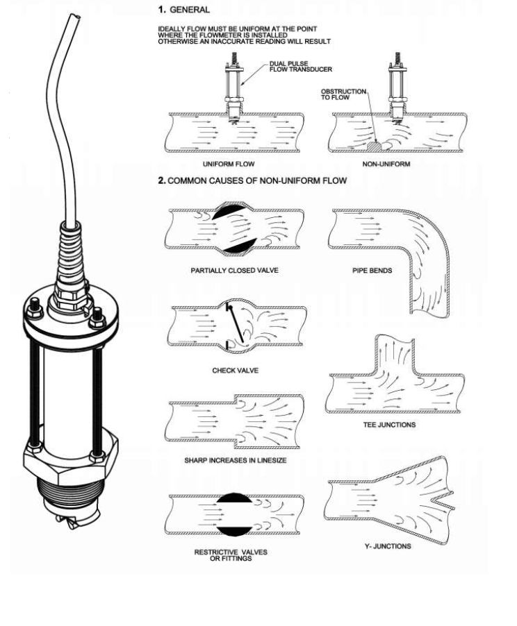
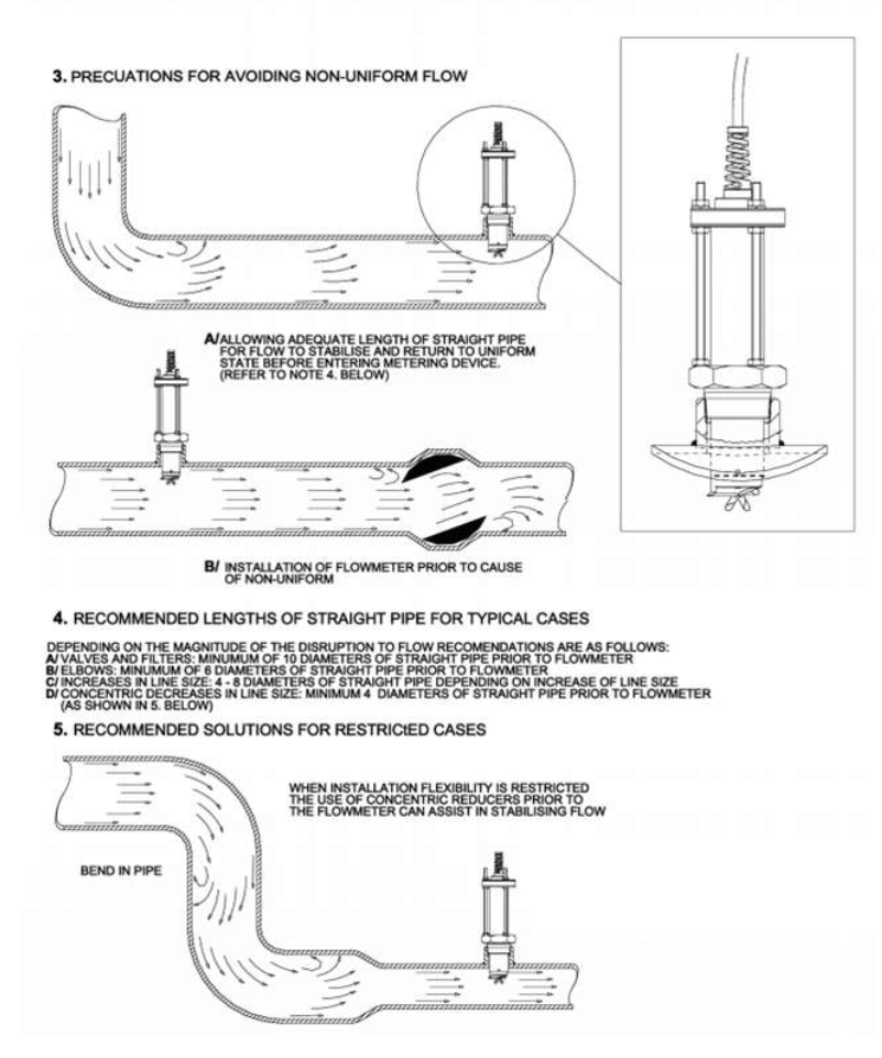
To be considered alongside Rivertrace installation drawings included.
How It works
The Flow meter paddle wheel has a magnet on one of the paddles. This magnet passes a reed switch and generates a pulse where the two wires to the paddle wheel assembly will become “Closed Circuit” momentarily for each revolution of the paddle wheel. It is crucial to ensure that only one of the paddles on the paddle wheel is magnetic.
The “K-Factor” is the number of paddle wheel rotations per m3 of liquid passing the paddle wheel. This K- factor value is purely dependent on pipe size. (The larger the pipe, the less rotations / volume as the liquid is moving more slowly than it would in a smaller pipe at an equal flow rate).
The K-Factors can be found in the table below (This has been adjusted to suit the intrinsically safe Reed switch type flow meter);
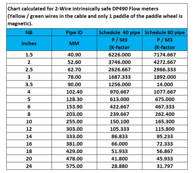
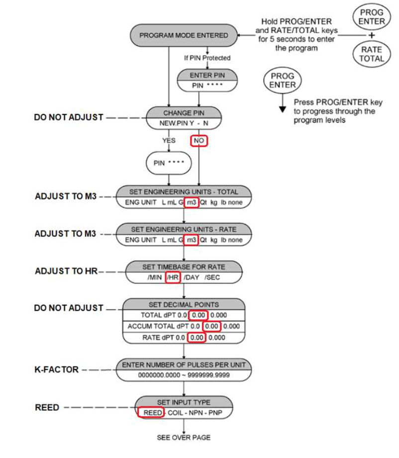
The K-factor must be entered into the flow meter totaliser. This is effectively its calibration.
The K-factor can be adjusted manually to increase accuracy where necessary. (If the k-factor is adjusted to a higher value, the displayed flow rate will decrease and vice versa.)
For pipes larger that 18” or 460mm I.D, the following conversion can be used to calculate the K-factor:

Setting the RT14 Flowmeter totaliser
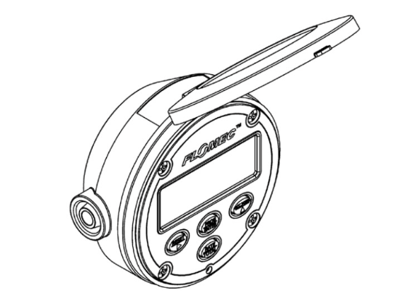
To enter the K-factor into the Flomec RT14 Flow meter, you must use the Flow meter totaliser interface:
Please note that the RT14 Flow meter has Blue rubber buttons. (The older RT12 flow meter totaliser has grey buttons that are part of the overlay).
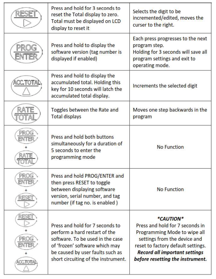
The Buttons on the Flomec totaliser have the following functions;
Menu Structure and what to adjust
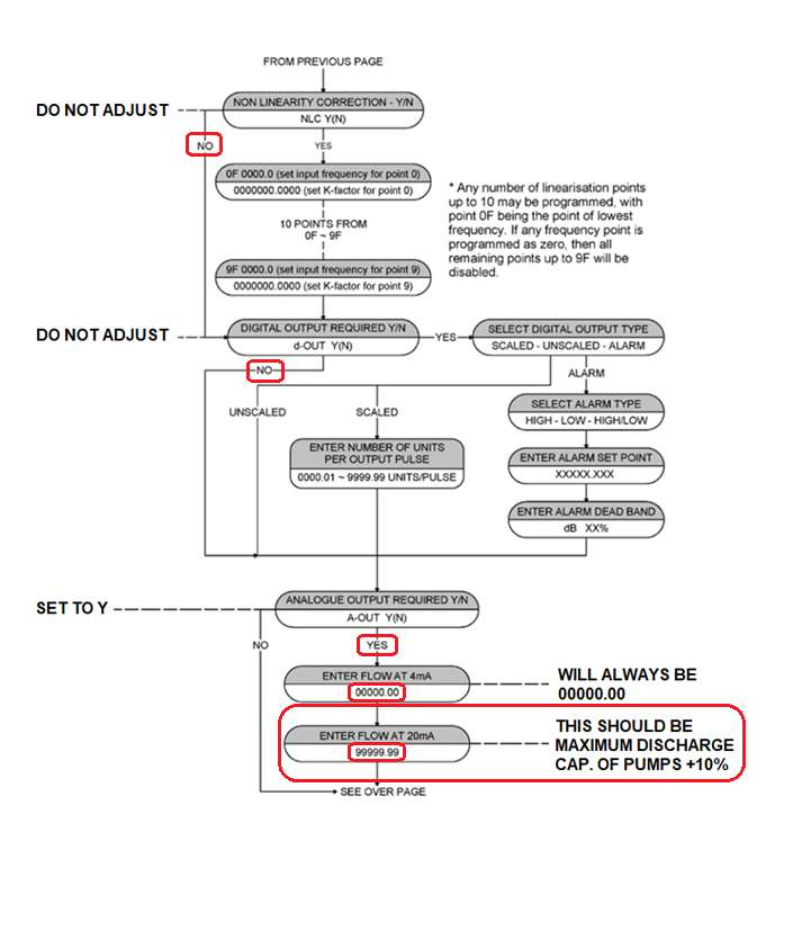
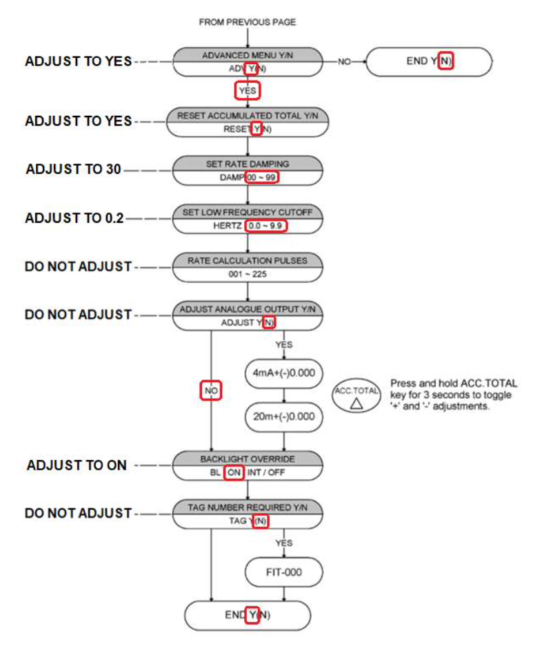
Once these settings are correctly entered, the flow meter totaliser will receive pulses from the paddle wheel and convert them to a passive analogue 4- 20mA loop signal. The power is supplied from the ODME Zener barrier module (At ~20V approximately. This varies).
The ODME computer module must now be adjusted to suit. At the ODME Computer module, adjust the AUTOCAP 1 Setting to match the setting entered at the flow meter totaliser for “ENTER FLOW AT 20mA”. This is the maximum capacity of the discharge pumps +10%. This has been circled in red in the menu structure section.