The ODME IO PCB is the large PCB mounted in the Smart ODME Computer module. This PCB distributes the power to the ODME computer, houses the control relays for the system, houses the hardware settings jumpers and communicates with the measuring cell over RS485. If you are experiencing problems relating to any of the above, the computer PCB may need replacing.
To replace the PCB, care should be taken to ensure no screws or parts are lost and that all hardware jumper settings are fitted correctly and in the correct positions. Antistatic precautions should always be taken when working on electronics or electrical components.
-PNG.png?width=550&name=PSU%20Front%20(002)-PNG.png)
Isolate all power to the ODME Computer and Zener barrier modules, ensuring all green plugs are marked up at the back of the ODME computer. A permanent marker pen should be used to label these plug J1 to J31.

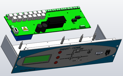
Once the power is isolated and all plugs are marked, remove the computer from the console and the plugs can be removed. The 10x Pozi screws to the top cover of the computer module can then also be removed.
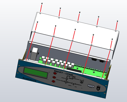
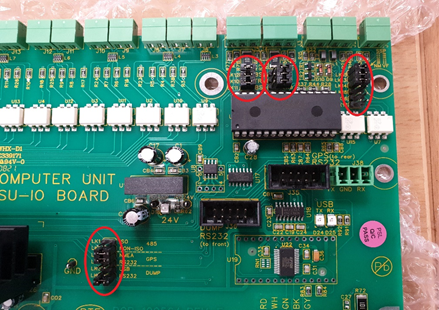
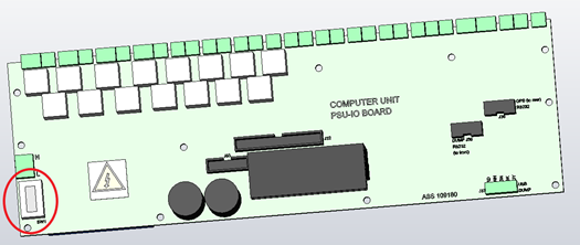
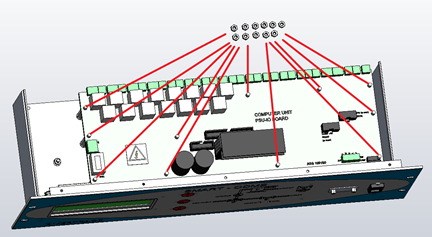
Once the top cover is removed, the large PCB in the base of the computer module is expose. This is the IO PCB. Photographs of this PCB Should be taken in this state so that you have a definitive record of all jumper settings, ribbon cable positions and voltage switch position. The hardware jumper settings and Voltage switch are circled below and will vary from ship to ship.
The rear of the Computer module can now be removed by unscrewing the 5X Pozi screws under the computer detailed below.
-png.png?width=550&name=PSU%203%20L%20(002)-png.png)
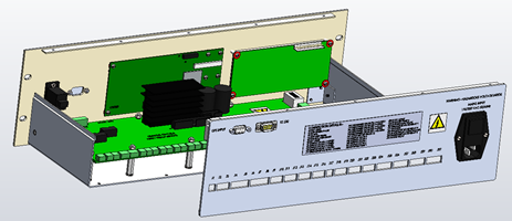
Remove all ribbon / internal power cables from the IO PCB and then remove the 11 X 7mm nuts and washers fixing the IO PCB in place.
The IO PCB Can then be lifted away and packed safely in an antistatic bag or antistatic bubble wrap.
Ensure that all hardware settings jumpers on the new PCB match the hardware settings jumpers on the old PCB and that the voltage selector is set correctly.
Refit the new PCB in reverse order to removal of the old PCB, reassemble the computer module, refit all external plugs and refit the computer module to the console / mounts.
The computer module can now be energized and tested to ensure the original problem has been resolved.