Rivertrace are world leaders in the measurement of free oil in water.
What are the rules and who do they apply to?
According to the Marine Environment Protection Committee, also known as MEPC, all oil tankers of 150 gross Tons and above, with a keel laid or a similar stage of construction on or after the 1st January 2005 must operate in accordance with a set of guidelines called MEPC.108(49). This is enforced globally and failure to comply can result in fines in excess of $1million and vessels detained. Marine pollution prevention is taken very seriously.
The discharge can take place when carried out using an approved ODME system (Oil Discharge Monitoring Equipment). This equipment is usually made up of an oil content meter, Flow meter, control and Data storage module and GPS. Rivertrace's solution is the SMART ODME.
MEPC.108(49) was adopted on the 18th July 2003 and is still current today. If the oil tanker is required to carry newer Bio-Fuel cargo oils, an additional guideline must also be adhered to called MEPC.240(65). This is an amendment that was introduced on the 27th May 2013, to work alongside the standard MEPC.108(49) regulation, specifically relating to the carrying of Bio-Fuels.
Engineers working with equipment relating to these guidelines must ensure that they are familiar with them to ensure that their work does not impact the compliance of the vessel.
What is Tank Washing water?
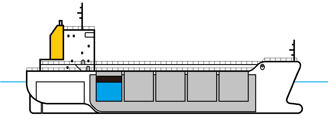
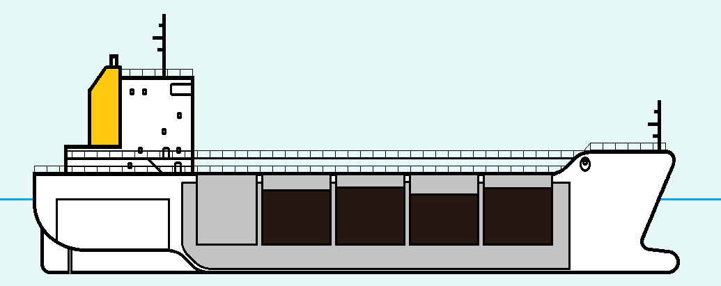
Onboard oil tankers, the cargo oil is transported in large tanks that are located down the deck of the vessel, within the hull.
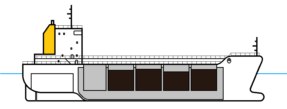
Within the hull, the tanks are segregated into multiple sections with Port and Starboard separation. This is designed like this for two main reasons; different cargo types and to balance the vessel. Typically, around 10 tanks but this is not a rule.
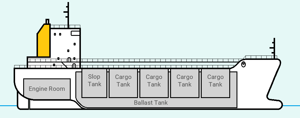
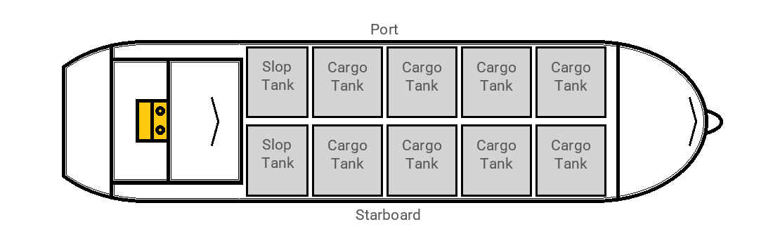 Once a cargo is offloaded and before a new cargo of a different oil type can be loaded, the tanks are washed with seawater using techniques such as high pressure hoses. This prevents contamination from different oil types that are carried by the vessel. Once the tanks are washed, the oily water is collected at the bottom of each tank. This waste water is then pumped out and stored in the tanks at the rear of the vessel referred to as the "Slop Tanks". This water is called "Tank Washing Water", also commonly referred to as "Slop Water" or "Slops".
What can the crew do with Tank Washing water?
It is legal for vessels to discharge Slop water back into the ocean providing that certain parameters are met. Uncontrolled levels of oil discharged into the ocean can have a dramatic impact on the environment. Oil in water is hazardous, leaving a sludge which can endanger marine life and the surrounding environment.
How is it discharged?
To be able to discharge the slop water in accordance with MEPC.108(49) guidelines, the slop water must have settled in the tank for as long as possible to allow gravity to separate the oil from the water.
In time, the oil will rise to the surface whilst the water will sink to the bottom of the tank. The point where the oil meets the water is called the oil / water interface.
In rough seas, this separation process can take a longer time as the water is constantly churned by the ocean.
Large pumps in the slop tank are used to discharge the slop water, up to the point of the oil / water interface, overboard. The pumps are usually capable of discharging around 300m3 of water per hour and in some cases, this can be as high as 3000m3 of water per hour.
Due to the size and power of these pumps, it would be very difficult for the large discharge pumps to remove the last remaining remnants of slop water from the slop tanks without sucking oil in from the surface of the slop water. For this reason, smaller pumps are fitted alongside the large pumps which are designed to handle small quantities of fluid. These smaller pumps are called stripping pumps and capable of discharging the very last quantities for slop water.
Once the large pumps have discharged the bulk of the slop water, the smaller pumps can take over to remove the remaining water below the oil / water interface, to complete the discharge.
Rivertrace SMART ODME MEPC.108(49) information
The Rivertrace SMART ODME System is designed and developed to monitor, control and record Slop water discharges from oil tanker vessels. The Rivertrace SMART ODME fully complies to MEPC.108(49) and MEPC.240(65) guidelines.

The standard ODME system is made up of the following modules, each module performing specific tasks to allow the system to function. These parts are mounted in various locations throughout the vessel.
Rivertrace SMART ODME Computer Module
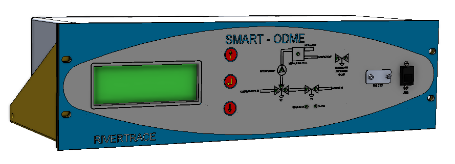
Typically mounted within the Cargo Control room, also known as the CCR, the SMART ODME Computer module controls all parts of the system alongside storing all data recorded during each discharge. This is the main user interface where the user can start and stop discharges, recall historic data, change settings and print logs (if the optional printer is supplied).
Rivertrace SMART ODME Zener Barrier Module
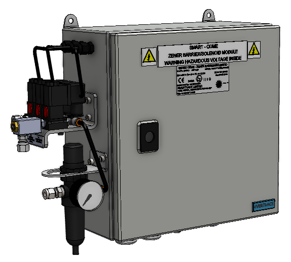 The Zener barrier module is typically located within the foam room and is the source of control voltages throughout the system. 110Vac or 230Vac is supplied to this module where it is stepped down to 24Vac before being utilized by the rest of the system for various signals. This Zener barrier module is also the interface between the safe area and the area onboard the vessel that may contain potentially explosive gases in the atmosphere. This module effectively acts as a fuse box, isolating any energy from passing to the hazardous area if a short circuit or unexpected high load is detected. Once a Zener has blown, the Zener barrier PCB must be replaced with a brand new PCB from Rivertrace as it is not compliant with our approvals to repair these PCBs.
The Zener barrier module is also the point where compressed air is connected to the ODME system from the vessel. Three solenoid valves mounted on the side of the enclosure will then open and close as required (determined by the ODME Computer module) to operate pneumatic components located in the hazardous area.
For vessels with pump rooms, the Zener barrier module may be found in the engine room.
Potentially explosive atmospheres are know as "Hazardous Areas" and are heavily regulated to ensure no dangerous equipment can be used in them. The Rivertrace ODME equipment designed to be used in or around hazardous areas is produced to comply with ATEX directives. Our designs are verified to comply with the ATEX directives by a certifying body called SIRA. Modification or manipulation of any hazardous area equipment onboard will void any hazardous area compliance certificate previously issued.
When talking hazardous areas, the correct terminology for an area where a safe, non explosive atmosphere is present, is known as a "Non-Hazardous Area".
Rivertrace SMART ODME VPC
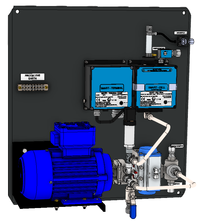
The VPC is a panel, usually mounted against the accommodation bulkhead on the main deck. This is a hazardous area so all equipment mounted here must comply to ATEX directives. The VPC comprises of three main parts, plus a wiring terminal box. These main parts are the Valve, Pump and Cell.
For vessels with pump rooms, the VPC Panel may be found in the pump room.
The Valve is a pneumatic 3-way valve that is controlled by the Zener barrier module via solenoid valves. This valve allows the ODME Computer to select between either clean water or slop water entering the pump. When no air pressure is applied, the valve will be positioned to allow sample water to enter the pump. When the valve is pressurised with compressed air sent from the Zener barrier module, the valve will open to allow fresh water from the ship to pass both through the pump and along the sample line to flush any debris that may have accumulated from previous discharges.
The Pump is part of a motor / pump assembly that is suitable for use in hazardous areas. The centrifugal pump not only increases the pressure to the measuring cell but also homogenises the oily water to ensure an even and consistent distribution of the oil particles in the water. This makes for more reliable and accurate measurements. On the inlet of the pump, a drain valve is fitted at the lowest point to allow the operator to drain all liquid from the system after each use. At the outlet of the pump, a pressure transmitter is installed to ensure the sample being pushed is at the correct pressure. If the pressure is above or below pre-set trip points, an alarm is generated at the ODME Computer module and the pump is stopped to prevent damage. The pump also has thermal overload protection and in some cases, a small heater to remove condensation in cold climates.
The Cell is one of the most important parts of the ODME system. Slop water is pumped through the cell where infrared light is used to determine the oil content of the slop water. There are no serviceable parts inside the measuring cell and security labels are fitted to ensure that this cannot be opened on site to prevent any damage occurring. The measuring cell is a calibrated part and all calibration data is stored inside it within the processor chip. The flow signal from the flow meter and the pressure signal from the pressure transmitter are also connected to the measuring cell. The measuring cell will compile the flow and pressure readings, along with the calculated oil content value (measured in PPM - Parts Per Million) into a digital signal and communicate these values with the ODME Computer (via the Zener barrier module).
Under MEPC. guidelines, the measuring cell must be calibrated every 5 years, or at the vessel's IOPP Survey, whichever is soonest.
Recalibration of the measuring cell must be carried out at Rivertrace using a complex calibration system. The calibration can also be renewed onboard by the crew by simply installing a new, calibrated measuring cell. This part is always supplied with a new calibration certificate to prove the date and accuracy of the calibration.
Different arrangements of VPC are available, suitable for different climates or specific ship requirements. Some older vessels have rules in place that disallow electric motors to be used in the VPCs location. In this situation, a pneumatic sample pump can be provided, negating the need to use an electric motor at the VPC.
Other vessels that are destined for use in extremely cold environments require insulated enclosures to be utilised to prevent the liquids involved from freezing.
The VPC is also available installed inside GRP, mild steel or stainless steel enclosures to provide both additional environmental and physical protection.
Rivertrace SMART ODME Motor Control Module
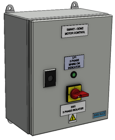
The Motor Control module is always located in a Non-Hazardous environment. This is typically mounted at chest height on the bulkhead inside the ships foam room. The Motor control module starts and stops the pump on the VPC as and when required to do so. This is controlled by the ODME Computer module.
For vessels with pump rooms, the motor control module may be found in the engine room.
Rivertrace SMART ODME Flow Meter Paddle Wheel
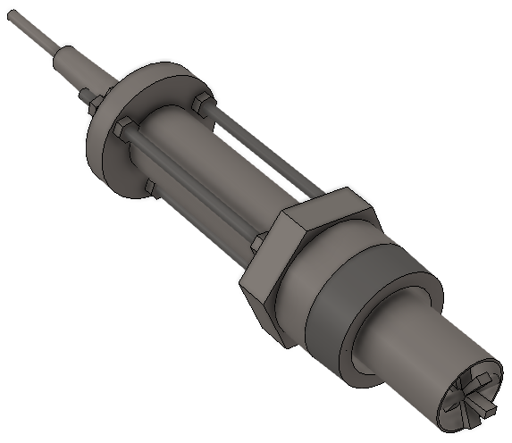
The flow meter paddle wheel is mounted inside the discharge pipe on the main deck, exposed to potentially hazardous atmospheres, and wired directly to the flow meter totaliser module. The flow meter paddle wheel is suitable for hazardous areas and is protected by Zener barriers mounted in the safe area within the flow meter totaliser module.
The flow passes the paddle wheel in the tip, causing it to spin. In one of the six paddles, there is a small magnet. As the paddle wheel spins, a reed switch in the paddle wheel probe housing closes its contacts each time the magnet passes. This momentary closed reed switch occurs at each revolution of the paddle wheel. We call this momentary closed switch state a "Pulse".
The calibration of the flow meter paddle wheel and flow meter totaliser essentially means telling the flow meter totaliser how many litres of water pass the paddle wheel for each revolution of the paddle wheel. The larger diameter of discharge pipe, the more water passes the paddle wheel per revolution. A thinner diameter pipe will mean that the flow will move faster than it would in a large diameter pipe at the same flow rate.
The flow meter must be accurate to 10%; however, accuracies around 2% are more of a reality once correctly calibrated.
Rivertrace SMART ODME Flow Meter Totaliser
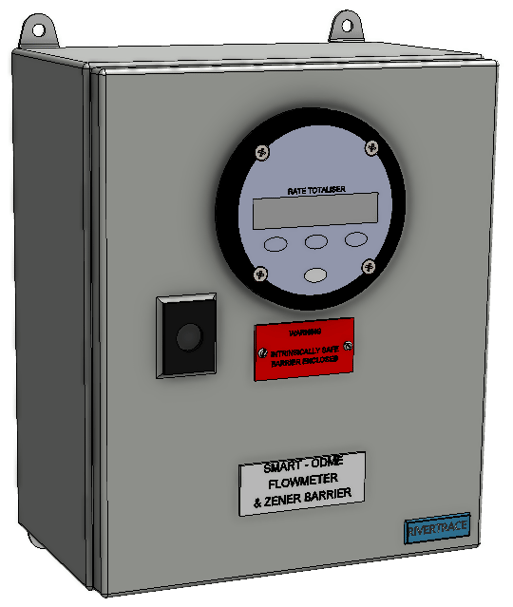
The flow meter totaliser is located next to the Motor Control module in the foam room. This module is connected to both the Flow meter paddle wheel (Fixed to the slop discharge pipe) and the ODME Measuring cell, via the Zener barrier module.
The flow meter totaliser receives pulses from the flow meter paddle wheel, calculates the flow rate in the slop discharge pipe and emits a signal that represents the flow. The signal is a 4-20mA Current signal.
Within the flow meter totaliser module, two Zener barrier devices are fitted to isolate the module from the flow meter paddle wheel that is located in the hazardous area.
For vessels with pump rooms, the flow meter totaliser may be found in the engine room.
Rivertrace SMART ODME Sample Probe
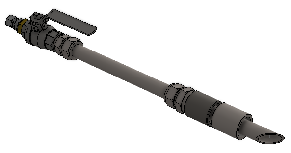
The Sample Probe assembly is mounted inside the discharge pipe on the main deck, exposed to potentially hazardous atmospheres. The probe is 316 stainless steel and must be inserted at an approximate depth of 25% on the internal diameter of the discharge pipe. The sample probe is complete with a manual isolation valve that must be open for operations and closed when the system is not in use.
The pipe from the rear of the sample probe must be fitted to the sample valve at the VPC via an additional pneumatic isolator valve (also part of our standard supply).
The 45% slash cut at the tip of the probe is designed to face the flow in the discharge pipe so that slop water is pushed into the tip. If this is installed incorrectly, facing away from the flow, the natural movement of the slop in the discharge pipe will try and draw the slop back from the ODME Pump.
Typical locations of Rivertrace SMART ODME components
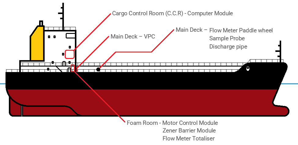
The Cargo Control room (C.C.R) is located at the front of the accommodation block, overlooking the main deck. This room contains a console used for controlling cargo, slop and ballast operations. It is clean, dry and air-conditioned. This is quite a central point of the vessel and often used as the meeting point between crew and external visitors, with its office-like environment.
The main deck is a harsh environment. Exposed to all weathers and of course, the ocean. Potentially explosive / hazardous atmospheres occur here and equipment used here should be approved for use in a potentially hazardous environment. The main deck is also covered in pipework from deck height, all the way up to a over 4 metres in some cases. This makes for trip and bump hazards.
The Foam room, sometimes called the Fire room, is positioned at the front of the accommodation block, at main deck level. This room is where fire safety equipment and systems are located such as alarms, dowsing systems and fire extinguishing foam tanks.
Vessels with pump rooms
Some vessels have a room called a "Pump Room" that is positioned between the engine room and slop tank. This is typically found on older vessels and is not very common.

The purpose of this "Pump room" is to house pumps in the hazardous atmosphere whilst the motors remained in the engine room - a non hazardous area.
With advances in technology and the acceptance of motors that are safe in explosive atmospheres, pump rooms are rare in new vessels.
Throughout this document alternative locations will be mentioned for vessels that are built with a pump room.

Where can a Tank Washing water discharge take place?
Amongst other factors, the vessel's speed and position dictate when a discharge of slop water can occur, according to MARPOL (The International Convention for the Prevention of Pollution from Ships).
As an overview, the below list highlights the key rules set out by MARPOL;
- The tanker is not within a special area.
- The tanker is more than 50 nautical miles from the nearest land.
- The tanker is proceeding en route.
- The instantaneous rate of discharge of oil content does not exceed 30 litres per nautical mile.
- The total quantity of oil discharged into the sea does not exceed 1/30,000 of the total quantity of the particular cargo of which the residue formed a part.
Although MARPOL set the international regulation for pollution prevention, this is a minimum. Often nations, regions and even states have tighter restrictions to meet on top of these MARPOL regulations. Some special areas of ocean are protected and no discharges may take place at all.
Ultimately, the ship's crew are responsible for determining if the ship is in a location where a discharge is permissible.
To ensure that the discharge is compliant to the above points, the following actions are taken;
- The tanker is not within a special area.
- This is controlled manually by crew, cross-checking the vessel's location against charts (maps).
- The tanker is more than 50 nautical miles from the nearest land.
- This is controlled manually by crew, cross-checking the vessel's location against charts (maps).
- The tanker is proceeding en route.
- The Rivertrace Smart ODME system will automatically prevent any discharge unless the vessel's speed is equal to, or exceeding 7 knots. The crew will be responsible for manually preventing a discharge if the vessel is not "en route".
- The instantaneous rate of discharge of oil content does not exceed 30 litres per nautical mile.
- This is calculated and acted on automatically by the Rivertrace Smart ODME system. The ODME System is monitoring Slop water PPM, Vessel Speed, GMT Time, Date and Slop Discharge flow. With this data the ODME will automatically calculate how many litres of oil are being discharged per nautical mile travelled by the vessel. If the 30 litres per nautical mile limit is reached, the overboard valve is closed and an alarm is sounded at the Smart ODME computer module.
- The total quantity of oil discharged into the sea does not exceed 1/30,000 of the total quantity of the particular cargo of which the residue formed a part.
- At the ODME Computer module, prior to a discharge taking place, the crew must manually enter the permitted quantity of oil to discharge. Once the ODME Computer module calculates that this limit has been reached, the overboard valve is closed and an alarm is sounded at the Smart ODME computer module.
An example is, if the vessel was carrying 150m3 of a cargo, the slop discharge after this cargo must not exceed 5L total oil content.
- At the ODME Computer module, prior to a discharge taking place, the crew must manually enter the permitted quantity of oil to discharge. Once the ODME Computer module calculates that this limit has been reached, the overboard valve is closed and an alarm is sounded at the Smart ODME computer module.
Rivertrace SMART ODME Clean Ballast Discharge mode (Optional feature)
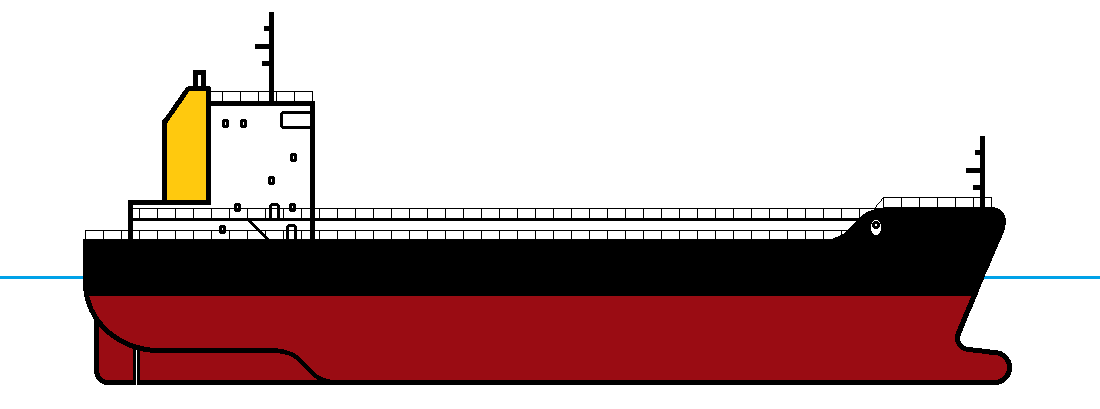
The cargo onboard the tanker is a huge weight and once the vessel is fully loaded, it will sit low in the water. The weight of the cargo and depth of the keel will keep the vessel stable on the ocean as illustrated below.
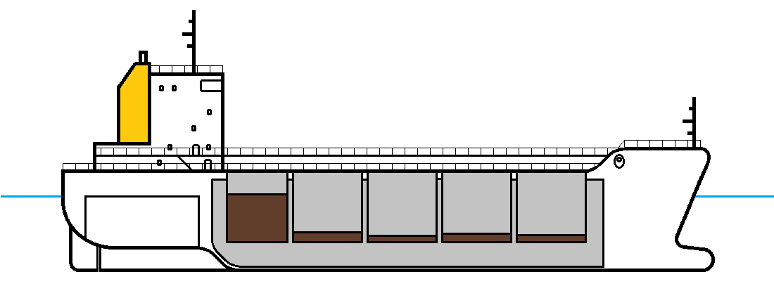
As the tanks are emptied, the vessel will rise in the water, reducing stability. This also exposes the vessel's high sides that can potentially act as a sail and impact the direction of the vessel.
To tackle this, the vessel is equipped with ballast tanks that run the length of the deck. These tanks can be filled with sea water to add weight where necessary. Adding weight (ballast) to tanks will balance the vessel and keep the ship sitting at the optimum depth. The correct terminology for the depth of the ship in the water is the "Draft". This is measured between the water line and the lowest point of the ship.
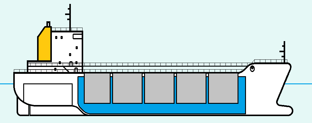
When the vessel takes on cargo oil once more, often in another port, the ballast water is discharged back into the sea to ensure the additional weight of the cargo oil does not overload the ship.
It is legal for vessels to discharge clean ballast water back into the ocean providing that the guidelines are adhered to;
- The oil content of the effluent without dilution does not exceed 15 parts per million
- The oily mixture does not originate from cargo pump-room bilges on oil tankers.
- The oily mixture, in case of oil tankers, is not mixed with oil cargo residues
On selecting clean ballast mode, an additional 3-way pneumatic valve (supplied as an optional addition to the standard Rivertrace ODME System) will open to allow a ballast water sample into the VPC instead of Slop water. The ODME computer will also apply an alarm point of 15ppm.
If the ballast water being discharged exceeds 15ppm, an alarm is raised at the Smart ODME computer module and the discharge is prevented.
What else happens?
Along with each discharge, the Rivertrace SMART ODME will automatically record data in accordance with MEPC.108(49) guidelines.
The following occurrences will trigger a log into the IMO data log, stored within the SMART ODME computer module;
- When the discharge is started.
- When the discharge is stopped.
- At intervals of not more than 10 min (except when the system is in stand-by mode).
- When an alarm condition develops.
- When normal conditions are restored.
- Whenever the computed rate of discharge varies by 10 litres per nautical mile.
- When zero-setting or calibration modes are selected.
- On manual command (Manual override of the ODME system).
For each data entry, alongside the cause of the data entry, the following details are recorded;
- Oil content of the effluent (Slop water) in ppm.
- Flow rate of discharge m3 /hour.
- Ship's speed in knots.
- Ship's position - latitude and longitude.
- Date and time (GMT).
- Status of the overboard discharge control.
All discharges of oil from the vessel must be recorded in the Oil Record book according to MEPC.108(49) guidelines.
Who Checks?
There are numerous ways of illegal discharges or even discharge data discrepancies being highlighted to authorities. Whistle-blowing is one method, where crew may witness illegal discharges taking place maliciously or even accidentally and report it. This is usually financially incentivised by authorities to encourage this to happen.
3rd parties such at neighbouring vessels or coastguards may also witness illegal discharges or even the resulting oil spill from an illegal discharge and track which vessel may have been responsible using the GPS locations of vessels that have been in the area.
The vessel may have accidently performed an illegal discharge and inform the authorities of this, taking the appropriate action to correct the mistake.
Sometimes no discharge is necessary for fines to be issued. Often, data discrepancies between the SMART ODME data, tank levels and the oil record book suffice. These discrepancies are usually picked up by official surveyors who survey vessels each time a port visit is made. In general, the surveyors who board the vessels in port will inspect this data.
To demonstrate the accuracy of the SMART ODME measuring cell, Rivertrace have developed a verification solution. This solution can be poured into the measuring cell by crew and the PPM displayed at the ODME computer module should read 500ppm +/- 10%.
Support
Alongside our expansive agent network, Rivertrace are embracing digital and all it has to offer. One aspect of this that is proving invaluable is our ever growing "Knowledge base", which is published on our website. The vast majority of queries from vessels, service engineers and others, outside of and within Rivertrace are published and explained here. This area is dedicated to "How To" guides, fault finding instructions, standard procedures and expert advice.