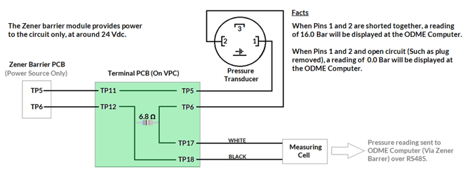
Smart ODME Pressure transducer information.
This page will give an understanding of how the pressure transducer should work within your ODME System.
It is essential that all wiring is fully checked prior to undertaking further fault finding. "Pull testing" each termination will also help identify poor terminations.
Always work in accordance with your ship specific wiring diagrams provided in your operating manuals.
Poor wiring is the number one cause of pressure monitoring circuit failure.
How it works
The pressure transducer operates at around 24Vdc. This voltage is supplied by the Zener barrier PCB (Smaller PCB mounted in the front of the Zener barrier module).
The pressure transducer will alter the current within this circuit, depending on pressure and this variation in current is measured by the ODME Measuring cell.
The measuring cell will take the analog signal, convert it to a digital value and then share the value with the ODME computer in the RS485 communication protocol.

With the wires removed from TP5 and TP6 of your Zener barrier module PCB, you should measure a DC voltage across TP5 and TP6 of around 24V (This could be between 18V and 30V). If this is not present, the Zener barrier PCB will need replacing.
With the wires reconnected to TP5 and TP6 of your Zener barrier module PCB, you should also be able to measure this voltage (between 18V and 30V), across the following points:
- Terminals 1 and 2 of the pressure transmitter.
- Terminals TP5 and TP6 of the Terminal PCB (Mounted on the VPC).
- Terminals TP11 and TP12 of the Terminal PCB (Mounted on the VPC).
The measurement will give you ~6.8 ohm .
- Terminals TP17 and TP18 of the Terminal PCB (Mounted on the VPC).
The current should also be measurable by connecting a multimeter in series within the circuit.
4.00mA = 0.00 Bar / 20.00mA = 16.00 Bar
- By Removing the plug from the pressure transducer, a reading of 0.00 bar should be obtained at the ODME computer module.
- By linking out terminals 1+2 of the pressure transducer plug, a reading of 16.00 bar should be obtained at the ODME Computer module.
