Smart PFM Overview
A look at the Smart PFM 107 and what makes it stand out over traditional sample analysis techniques.
Smart PFM 107 Overview
All details regarding the serial number, supply voltage, date of manufacture and approvals can be found typed onto the silver rating label, fixed to the top left corner of the Smart PFM107 backplate.
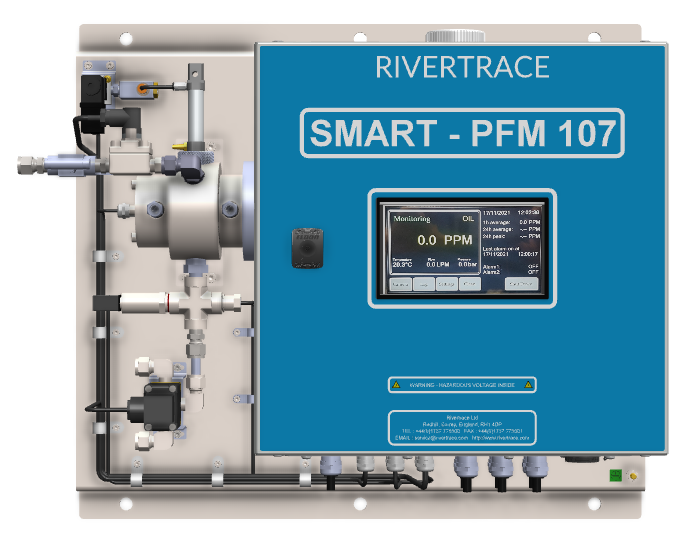
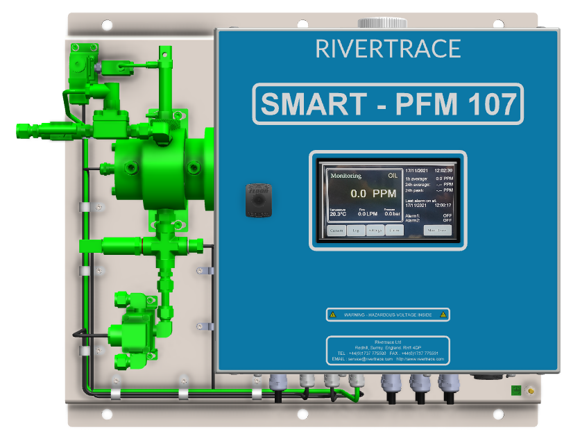
The Smart PFM107 monitor is split into two modules; the Computer module and the measuring cell.
The controller module, located on the right of the SmartPFM107, performs the following;
- Houses and drives the Display where Time, Date, PPM, alarm states and fault messages are visible.
- Houses and drives the touch screen used to navigate the menus.
- Receives mains power and distributes power to the measuring cell.
- Contains two alarm relays. Alarm 1 (Left Relay) must be used for directly controlling an "Automatic Stopping Device" and Alarm 2 (Right Relay) is used to control an audible alarm supplied by the vessel.
- Drives the sample / Clean solenoid valve as required.
- Holds the Clock and IMO Data memory.
- Has a mA output terminal that will emit an active 4-20mA Output, representing the PPM value, for remote displays.
- Has a switch input that MUST be wired to volt free contacts within the separator that close when the oily water separator is running. This is a legal requirement. This is the "Separator Input Status".
- Holds the Calibration data.
- Houses the microscope used for detecting oil and other contaminants within the sample.
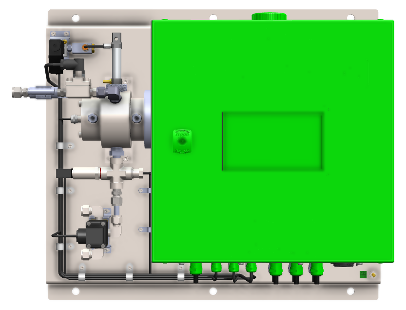
The measuring cell, located on the left of the Smart PFM107, performs the following; All wetted parts are 316 Stainless steel to stand up to harsh environments and samples that are typically too damaging for standard oil-in-water analysers.
- Houses the precision optics to allow the camera located inside the computer module to accurately photograph the oily water sample.
- Houses a blue strobe back light to allow the camera located inside the computer module to accurately photograph the oily water sample with clear and crisp image outlines.
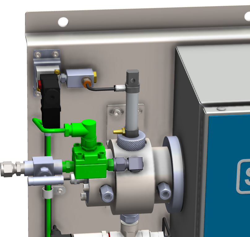
- Houses the flow meter that will measure sample flow passing the measuring cell, tripping the alarms if insufficient flow is detected.
- Houses the pressure transmitter that will measure sample pressure within the measuring cell, tripping the alarms if insufficient pressure is detected.
- Houses a thermistor that will measure sample temperature within the measuring cell, tripping the alarms if the temperature is out of tolerance.
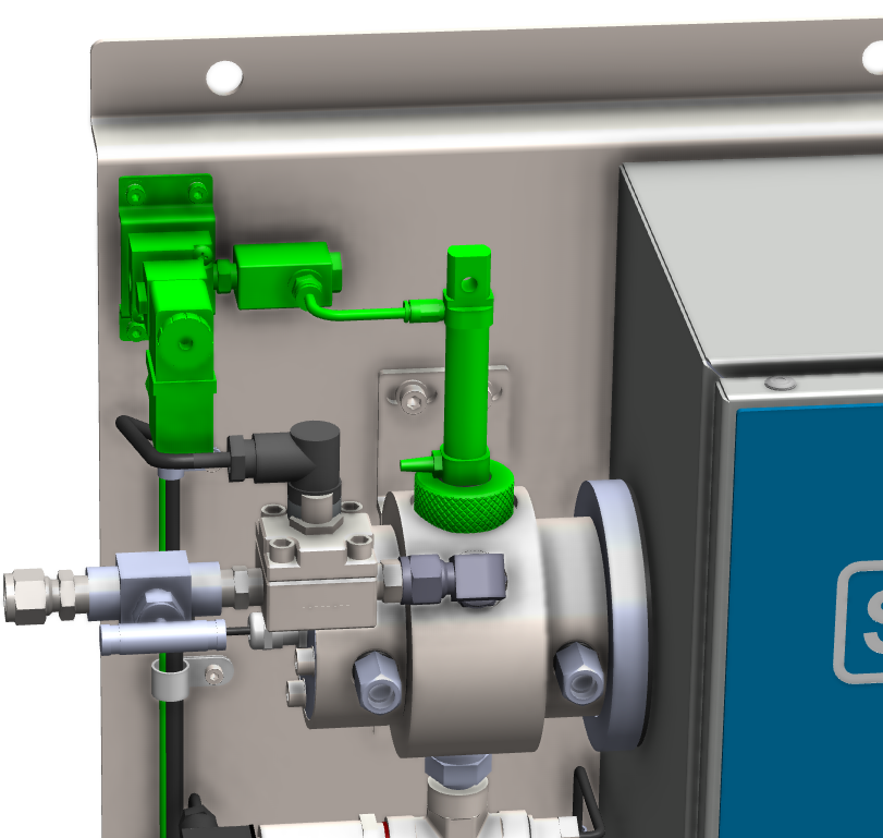
- Houses the Autoclean actuator that is used to ensure that the optical path and sample windows are kept at optimum clarity.
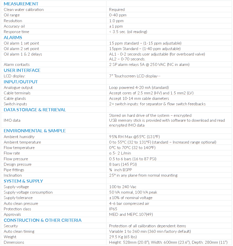
The Smart PFM107 meets or exceeds all requirements set out by MEPC.107(49). The specifications in the table below are for our standard offering.
As with all MEPC.107(49) Oil in water analysers, there are flaws within the regulation that do not protect against malicious or even accidental tampering of the OCM. Rivertrace have identified these areas and have robust solutions in place to bolster the standard Smart PFM107 OCMs security and reliability.
The most prominent cause of OCM failure is undoubtedly soiling of the optical components within the measuring cell. Rivertrace have factory standard accessory to tackle this manufacturer wide problem. A pneumatic Auto-Clean system is fitted to all standard Smart PFM107 analysers to automatically clean the optics on adjustable, timed intervals. With crew already stretched, this system increases service intervals and reduces man hours needed for periodic maintenance.
Another known problem with OCMs on board vessels is that the flow through the measuring cell is rarely checked. This means that it may be possible to trap clean water inside the measuring cell to allow a discharge to take place without measuring the oil content of the actual water leaving the OWS and passing overboard. The result is an unmonitored, illegal discharge. This can occur through a malicious act by OWS operators or due to something as simple as a blocked sample pipe.
Whatever the cause, Rivertrace have a solution in which a flow meter is fitted to the measuring cell outlet. If the flow passing through the measuring cell does not meet the required rates , an alarm is triggered and the automatic stopping device (3-way valve) at the separator outlet is closed to recirculate all flow back to the bilge tank until flow is detected once more.
On top of these enhancements that exceed standard MEPC 107(49) requirements, Rivertrace offer a verification sample kit that can be used by crew to verify and demonstrate the accuracy of the Smart PFM107 measuring cell. Two bottles of fluid are provided per kit allowing the operator to demonstrate the accuracy at both 10ppm and 20ppm. These points have been selected so that they straddle the alarm point which is typically set to 15ppm. The 10ppm verification kit will demonstrate that the Smart PFM107 monitor will allow a discharge when the PPM is below the alarm point. The 20ppm solution will demonstrate that the Smart PFM107 will prevent a discharge should the PPM rise above the alarm point at 15ppm.
The Factory calibration is valid for 5 years. The calibration can only be performed by Rivertrace at the Rivertrace factory or by specially trained and certified engineers on-site, renewing the calibration certificate for a further 5 years.
Why choose Microscopy over traditional oil-in-water measurement techniques?
Although the Smart PFM has very similar function to the Rivertrace Smart Bilge monitor and OCMs from competing manufacturers, the Smart PFM107 is a very different analyser when it comes to performance, primarily designed for applications that call for an MEPC.107(49) approved analyser to be used in applications that fall outside of the standard bilge water discharges.
Typically, there are two main measurement techniques employed to measure oil in water, being UV fluorescence and scattered light. These technologies are very common, with scattered light technology being far more widely utilized, and can perform very well in the right applications.
UV fluorescence is extremely accurate when measuring known oils in known water, often offering +/- 0.1ppm accuracy estimates and better, depending on measurement range. It is important to read the small print with these analysers as the conditions that must be met to achieve these accuracies are typically very difficult to achieve in a real working environment, outside of laboratory conditions. This is ideally suited to drinking water applications and similar, where the composition of the sample is regular and predictable, without unknown contaminants. The downside to this technique is that when unexpected substances within the sample fluoresce, such as cleaning chemicals, soaps and BOP fluids, the UV fluorescence technique can give hugely inaccurate results. High calculated readings can be common and discharges of oil-free fluids can be prevented due to these false readings.
Scattered light is predominantly used in bilge discharge or other dirty water applications where unknown substances may be found within the sample. This technique gives average to good accuracy across a wide range of sample conditions, however, anything that scatters light within the sample has the potential to increase the oil content reading (Solids behave very differently to oils and other light scattering contaminants so can usually be largely ignored by the algorithms calculating the oil content) . Accuracies around +/- 2.0ppm and better are usual and are generally quite reliable when used in the field. If a substance does not change the clarity of the sample, it is unlikely that the analyser will detect the substance as an oil or any other component that will raise the calculated value. The Achilles heel of scattered light measurement techniques is that if the sample contains non-emulsifying soaps, bacteria, algae or other contaminants that alter the turbidity of the sample, the monitor is likely to overread, preventing discharges of fluids that may be perfectly suitable to discharge.
Here is where the Smart PFM, using Microscopy as its measuring technology steps up.
Microscopy excels due to the silhouette of the oil content being visibly identified and measured, the optical clarity of the sample has very little impact on accuracy and is immune to algae, bacteria, dissolved chemicals and dissolved solids hindering the data capturing under the microscope, up to circa 160 NTU.
The Smart PFM107 continuously monitors and regulates the image intensity and sharpness at the digital camera that is obtaining the images of the sample through the microscope. As the turbidity of the sample fluctuates, the power to the backlight strobe increases and decreases to maintain a clear image suitable for shape detection of particles within the sample.

As a high level overview of the method of image analysis, there are three main categories that particles fall into.
Free Oil particles are typically spherical and give a circular silhouette with a dark centre.
Solids can appear in many forms and are typically irregular with a dark centre.
Gas bubbles within the sample behave like a lens and focus the backlight into a very bright centre. Often, the centre of a gas bubble is brighter than the surrounding clear water.
This technique offers all of the advantages and positive behaviours of scattered light technology with the additional benefit of handling the turbid water that can usually be found in applications where water may stay static for extended periods of time, harbouring algae or bacteria blooms or water that has been contaminated with other chemicals, BOP fluids etc. that will increase sample turbidity up to approximately ~160 NTU. Chemicals and other non-oil based substances that fluoresce will also pass through the Smart PFM107 unnoticed, resulting in a very reliable measuring technique that will not leave the operator with a quantity of water that they cannot discharge due to false high readings.
Maintenance
Weekly
• Confirm the instrument reads 0 ppm when clean water is passed through the cell.
• Engage manual cleaning actuator to force alarms and confirm that all alarms are ON.
Yearly
• At yearly intervals (or when necessary) the wiper ring on the cleaning system assembly should be
replaced. This can be ordered from Rivertrace as part number: 111722.
• It is advised to verify the calibration of the system on a yearly basis. It is possible to verify the
accuracy of the monitor by purchasing a Calibration Check kit. This can be purchased directly from
Rivertrace, one of our agents or service centres. If the calibration check is carried out by one of our
service centres, then a calibration check certificate will be issued by them on behalf of Rivertrace.
5 Years
• The Measuring cell should be verified by a Rivertrace approved service centre.
Spare parts
| Item | Quantity | Part number |
| Cell wiper ring | 2 | 111722 |
| Cleaning Kit | 1 | 110707 |
| Desiccators | 2 | 111389 |
| Membrane overlay | 1 | 111381 |
| LCD display module | 1 | 111580 |
| IP 65 memory stick cover | 1 | 111528 |
| IP 65 Ethernet connector | 1 | 111509 |
| 3 way valve (24V DC) | 1 | 111419 |
| Air solenoid valve (24V DC) | 1 | 111437 |
| Calibration verification Kit | 1 | 112137 |
