Introduction
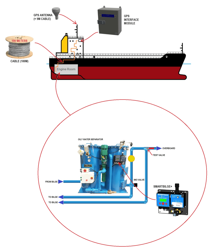
The SMART BILGE + GPS Hardware kit offers the ability to record the ships speed and position
alongside each IMO data entry. Alongside recording this information, the SMART BILGE + will
generate an alarm and prevent all discharge if the ship's speed falls below a pre-set trigger point.
This ensures that no discharge can take place unless the vessel is underway, in accordance with
MEPC requirements,
This kit is supplied with 100 meters of 1 pair screened cable for use between the SMART BILGE+
monitor and the GPS Interface module and 9 meters of cable to use between the GPS Antenna
and GPS Interface module.
It is assumed that the installer will ensure that he will isolate power when carrying out the installation and will not work on live equipment.
Installation kit
The installation kit for the SMART BILGE + GPS Hardware kit (part number 113616) contains the following parts:
| 109911 | GPS SENSOR WITH 30ft CABLE |  |
| 109930 | SATELLITE PSU/INTERFACE MODULE ASSEMBLY |  |
| 109348 | CABLE 2 CORE SCREENED | 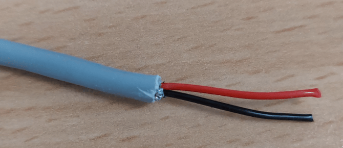 |
| 105295 | CABLE 3 CORE 1.5mm2 OD 9.3 mm (Power) | 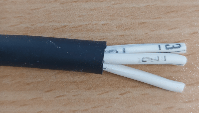 |
| 104642 | BOOTLACE WHITE 0.5 x 8mm |  |
Instructions
Preparing the SMART BILGE+
Remove the front cover from microcontroller module using a small Philips screwdriver, then remove the clear protective cover within the enclosure using a small flat bladed screwdriver.
Mechanical Installation.
The Antenna must be mounted at the highest available point of the vessel and unobstructed by nearby structures. An area that does not see shadows from the sun throughout the day is a good indication or a suitable location.
The GPS interface module must be mounted within 9 meters of the GPS antenna in a dry location. The 9 meter cable must be run between the GPS antenna and the GPS interface module.
The screened 2 core cable must be run between the GPS interface module and the SMART BILGE+.
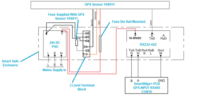
Wiring Installation
The wiring should be installed according to the following diagram.
The wires must be cut to the required lengths and the ferrule bootlaces 104642 attached to each bare wire core.
Cables must be passed through glands when inserted into the SmartSafe and SMART BILGE+ enclosures.
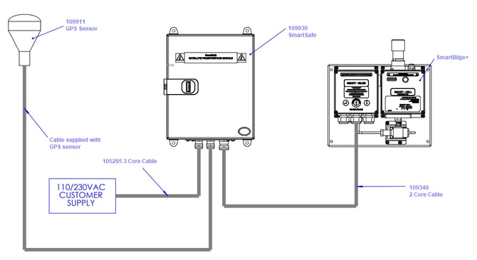
The connections for the cables can be observed in the following image.
When all the wiring is installed, reattach the protective cover and front cover on the SMART BILGE+ then tighten all glands used before reinstate power to the system.
Enabling the GPS
The GPS system will now need to be enabled using your unique SMART BILGE+ activation PIN. Please contact sales@rivertrace.com to obtain the PIN. This will be specific to your PCB serial number so please ensure that this is included with your enquiry.
Testing the GPS
You can observe the GPS values on the SMART BILGE+ interface by scrolling to "VIEW INPUTS" on the main menu then selecting "VIEW GPS".
These values should align with the devices current location.
Maintenance
COMING SOON.