Smart ODME RT12 Flow meter totaliser and DP490 Flow meter paddle wheel details
This page explains how the RT12 Flow meter totaliser and DP490 flow meter paddle wheel work and how to diagnose and resolve any issues you may experience.
Smart ODME RT12 Flow meter totaliser and DP490 Flow meter paddle wheel details
This page explains how the RT12 Flow meter totaliser and DP490 flow meter paddle wheel work and how to diagnose and resolve any issues you may experience.
Overview
The Smart ODME Requires a flow meter to provide the actual flow rate of discharge leaving the vessel that is being monitored by the ODME System. Rivertrace's solution of obtaining this flow value is the DP490 paddle wheel, paired with the RT12 flow meter totaliser (This has now been superseded by the RT14 totaliser).
How it works
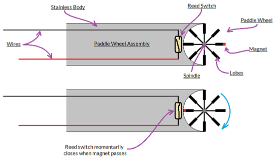
The paddle wheel assembly is mounted into the discharge line so that the flowing water can rotate the paddle wheel at the tip of the assembly. The faster the flow, the faster the paddle wheel will spin.
The paddle wheel has a magnet in one of the six "lobes" that will momentarily close a reed switch located in the the paddle wheel body. This allows the paddle wheel to give a "Pulse" across two wires leaving the paddle wheel assembly, each time the paddle wheel revolves. There is one pulse per revolution.

The two wires leaving the paddle wheel assembly are connected to the flow meter totaliser via two isolation barriers (The barriers act as a fuse between the safe area and potentially hazardous area and will permanently blow if potentially hazardous energy is detected in the potentially hazardous area).
The Flow meter totaliser receives the pulses from the paddle wheel and will count how many pulses are received over time. The totaliser can then compute the current flow rate using its internal calibration called the K-Factor. This is effectively the number of revolutions of the paddle wheel per volume of water. Once calculated, the flow meter totaliser will emit the flow rate as a passive 4-20mA Signal to the measuring cell, via the Zener barrier module.
At the measuring cell, the 4-20mA Signal will be detected and then sent to the ODME Computer within its digital RS485 data package, again, via the Zener barrier module.

Fault Finding
The first point to clarify is the nature of the fault. Please select the relevant option below to see detailed fault finding instructions for your issue.
