Checking the DP490 paddle wheel and RT14 flow totaliser
- The first steps are always to ensure that you are you certain that there is flowing water passing your flow meter. You must also double check that all wiring is installed in accordance with the Rivertrace drawings provided with your system. From now, these fault finding steps will assume that all wiring is terminated in accordance with the Rivertrace drawings.
- If you are certain that the water is flowing, you must now check the condition of the paddle wheel assembly, following the steps found here.
- If your paddle wheel assembly has been tested with positive results, you must now check that pulses are being received after the isolation barriers. Instruction on testing the barriers can be found here.
- If you are receiving pulses from your paddle wheel after the isolation barriers, you must now ensure that the flow totaliser settings are correct using the information found here.
At this stage, you have confirmed the following points:
- The Rotor is in good, clean, free spinning condition.
- Pulses are being sent from the paddle wheel assembly.
- The isolation barriers within the flow meter totaliser module are functioning.
- The settings within the flow meter totaliser are correct.
Checking the RT14 flow totaliser output to the ODME system
You must now check that the flow meter totaliser is interacting with the system correctly.
- First you must measure the mA output from the flow totaliser that is connected to the Zener barrier module following instruction found here.
- If your mA Signal is correct, you must now check that the signal is reaching the measuring cell correctly. you must first check the health of your Zener barrier PCB following the instructions found here. Instructions of checking the circuit between the TP5 / TP6 inputs at the Zener barrier PSU PCB and the measuring cell can be found here.
- To ensure that the mA signal is reaching the measuring cell, you must now check that 27mV is present across terminals TP9 and TP10 of your VPC terminal box (Mounted next to the measuring cell).
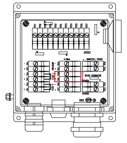
If 27mV is present and your ODME computer module will still not display flow, the measuring cell will require replacement.
If 27mV is missing, there is a problem with the wiring.